


Quick Research
Generate reliable direction feasibility study reports for your R&D in just a few steps.

Technical Q&A
Discover and master advanced knowledge NOW. Basics, ideas, possibilities, all at once.

Find Solutions
As an expert in R&D theories, this can generate solutions to your technical problems instantly.

Evaluate Feasibility
Analyze your overall solution with one click, know your potential R&D risks in advance.

Monitor Landscape
Get weekly tech updates, stay abreast of the latest tech innovations and key insights.
Belt pulley, crop raking mechanism and harvester
A pulley and belt technology, which is applied in the fields of pulleys, reeling mechanisms and harvesters, can solve the problems of small adjustable speed range and poor practicability, and achieve the effect of increasing the speed regulation range and enhancing practicability
- Summary
- Abstract
- Description
- Claims
- Application Information
AI Technical Summary
Problems solved by technology
Method used
Image

Examples
Embodiment 1
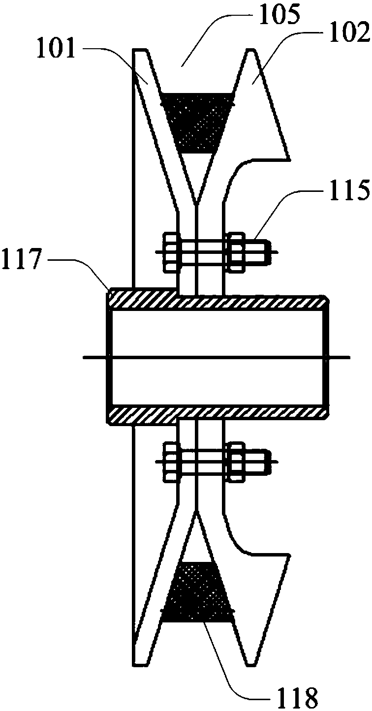
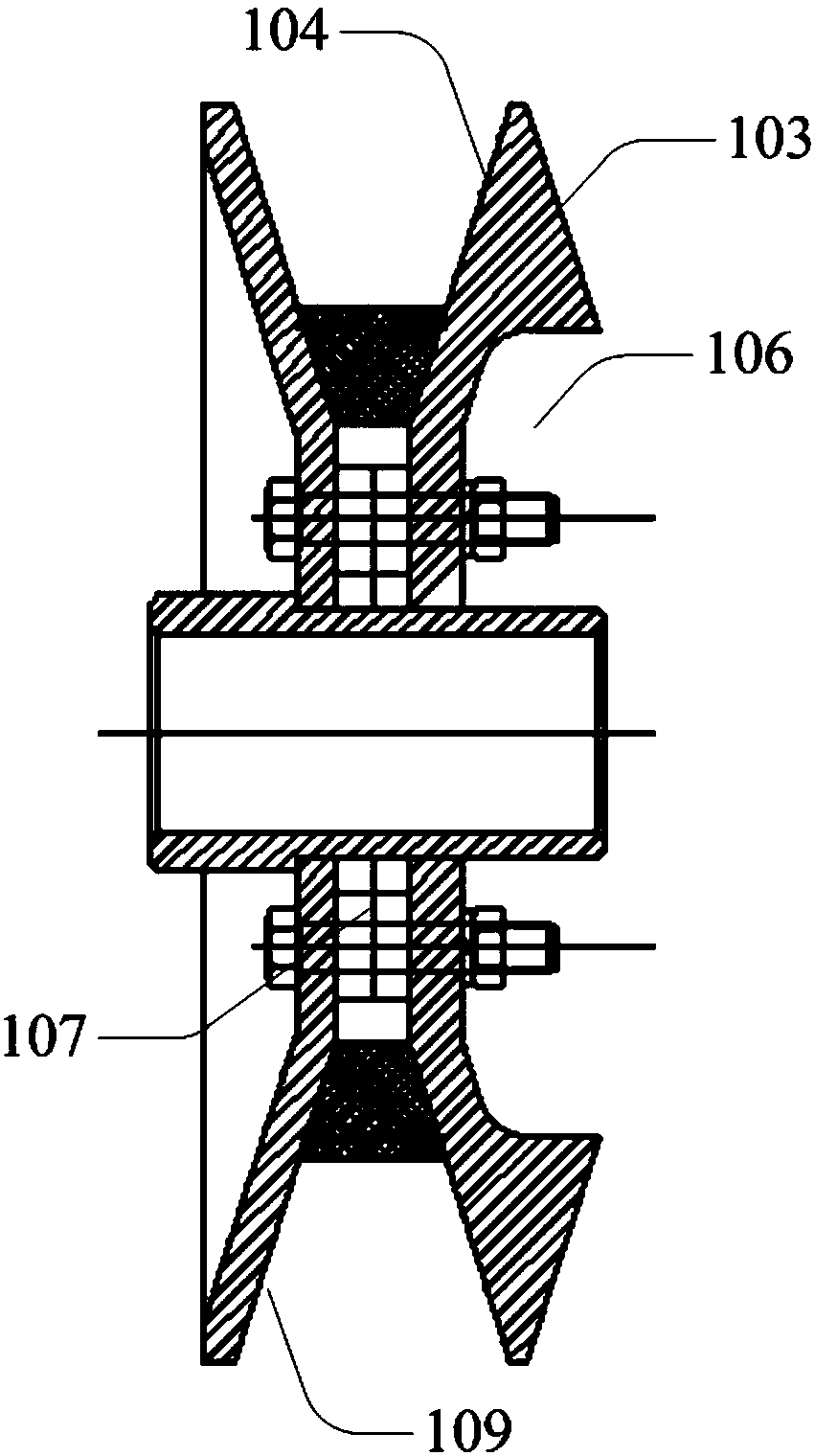
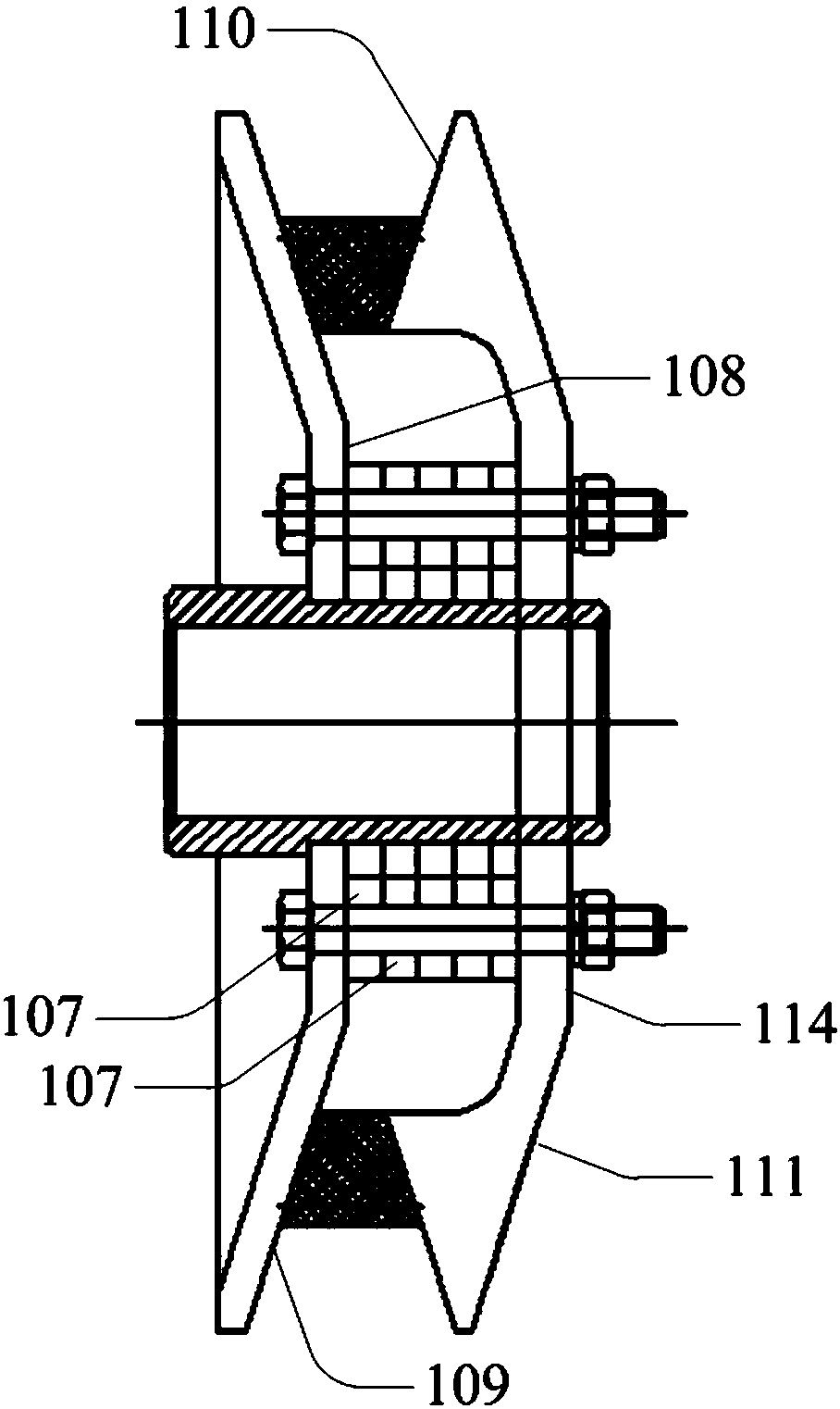
[0035] see Figure 1 to Figure 5 As shown, Embodiment 1 of the present invention provides a pulley, including a fixed plate 101 and a moving plate 102; and the second working surface 104 respectively facing the opposite direction; the first working surface 103 of the moving disk can form a belt groove 105 with the working surface of the fixed disk; the turning disk can make the second working surface 104 of the moving disk and the fixed disk A belt groove 105 is formed between the working faces.
[0036] Specifically, during use, the first working surface 103 of the moving disk can be made to face the working surface of the fixed disk to form the belt groove 105 for accommodating the V-belt, or the second working surface 104 can be aligned with the fixed disk by turning over the rotating disk. The working surfaces of the discs are opposite to form a belt groove 105 for accommodating the V-belt 118. The belt groove 105 is tapered, that is to say, the groove width of the belt g...
Embodiment 2
[0054] The pulley in this embodiment is an improvement on the basis of Embodiment 1. The technical content disclosed in Embodiment 1 will not be described repeatedly, and the content disclosed in Embodiment 1 also belongs to the content disclosed in this embodiment.
[0055] see Figure 6 As shown, in this embodiment, a second accommodating groove 116 is opened on the working surface of the fixed disk, which is used to accommodate the setting part of the first working surface 103 of the moving disk and / or accommodate the second working surface 104 of the moving disk. The setting part is used to adjust the width of the belt groove 105 formed between the fixed plate and the movable plate. By opening the second accommodating groove 116 on the working surface of the fixed disk, the adjustable width of the belt groove 105 can be increased, thereby helping to make the pulley have a larger speed regulation range, that is, to meet different harvesting conditions. The speed regulation...
Embodiment 3
[0057] This embodiment also provides a pulley. The pulley of this embodiment describes another implementation in which the width of the belt groove formed between the fixed plate and the moving plate can be adjusted. Other implementations The technical solution of Example 1 also belongs to this embodiment and will not be described again.
[0058] In this embodiment, a second accommodating groove is opened on the working surface of the fixed disk, which is used to accommodate the setting part of the first working surface of the moving disk and / or the setting part of the second working surface of the moving disk, so as to adjust The width of the belt groove formed between the fixed plate and the moving plate. It should be noted that, in this embodiment, neither of the two working surfaces of the moving disk may have the first receiving groove.
[0059] In summary, the pulley provided by this embodiment can increase the adjustable speed range of the pulley, meet the speed regula...
PUM
 Abstract
Description
Claims
Application Information
 - R&D Engineer
- R&D Manager
- IP Professional
- Industry Leading Data Capabilities
- Powerful AI technology
- Patent DNA Extraction
Browse by: Latest US Patents, China's latest patents, Technical Efficacy Thesaurus, Application Domain, Technology Topic, Popular Technical Reports.
© 2024 PatSnap. All rights reserved.Legal|Privacy policy|Modern Slavery Act Transparency Statement|Sitemap|About US| Contact US: help@patsnap.com