A carbon rod discharge screening device

A discharge sieve and carbon rod technology, which is applied in sorting and other directions, can solve the problems of general and carbon rod damage to the screening effect, and achieve the effect of convenient operation, high screening efficiency and simple structure

Active Publication Date: 2020-08-21
亳州市亚珠新材料有限公司
View PDF2 Cites 0 Cited by
  • Summary
  • Abstract
  • Description
  • Claims
  • Application Information

AI Technical Summary

Problems solved by technology

However, this kind of equipment still has the defects that the carbon rods may be damaged due to collisions during the screening process and the screening effect is general.

Method used


Image

  • A carbon rod discharge screening device
  • A carbon rod discharge screening device
  • A carbon rod discharge screening device

Examples


Embodiment 1

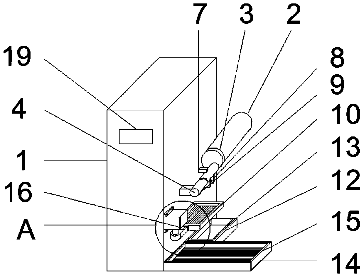
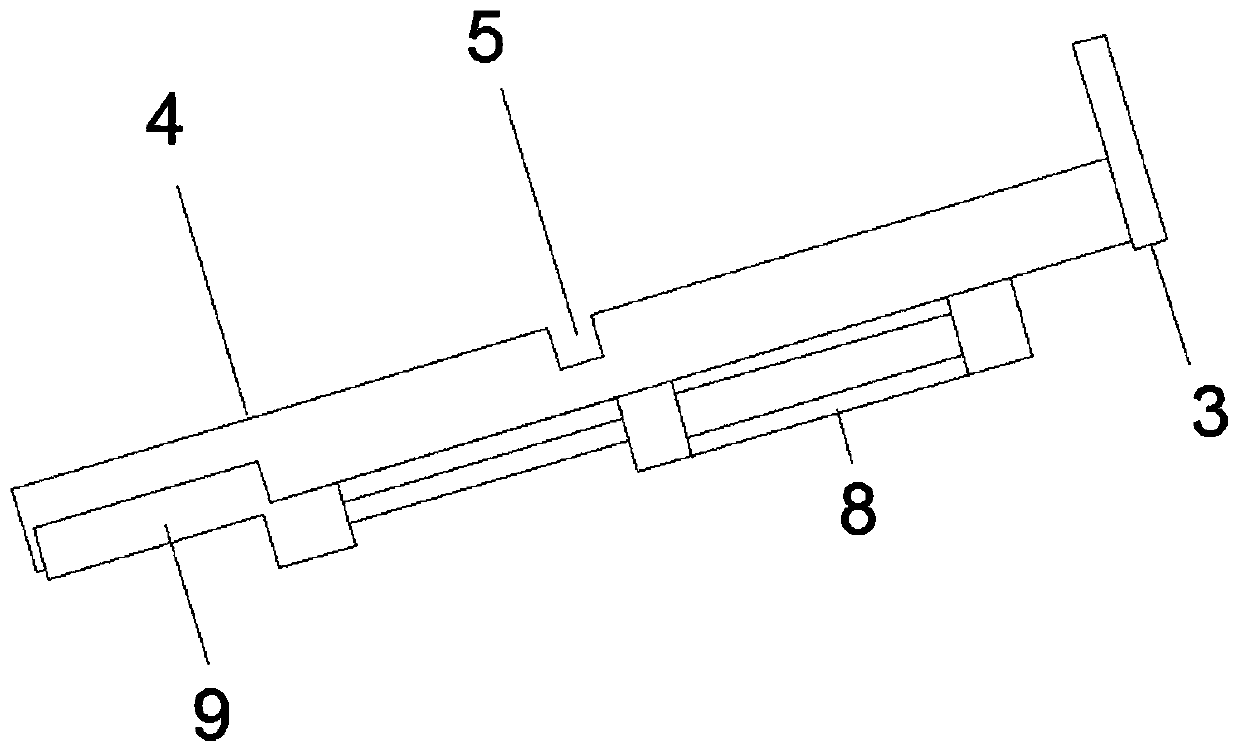
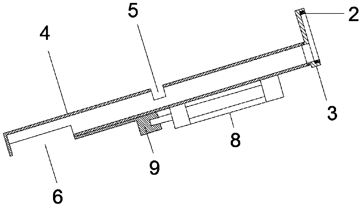
[0021] like Figure 1 to Figure 5 As shown, a carbon rod discharge screening device includes a support 1 and a controller 19 arranged on the support 1. The side of the support 1 is provided with a feed drum 2, a waste tank 12, a genuine product tank 14 and Photoelectric switch 7, the output end of described feed roller 2 is connected with roller cover 3, and described roller cover 3 is connected with guide tube 4, and the upper end of described guide tube 4 is provided with opening-5, and the lower end of described guide tube 4 Opening two 6 is provided, and described photoelectric switch 7 is located at the top of opening one 5, and the sidewall of described guide pipe 4 is provided with cylinder 8, and the piston rod of described cylinder 8 is connected with baffle plate 9, and described opening two 6 is provided with a material delivery frame 10 below, the side of the support 1 is provided with a first servo motor 11, the output shaft of the first servo motor 11 is connecte...

Embodiment 2

[0024] like Figure 1 to Figure 5 As shown, a carbon rod discharge screening device includes a support 1 and a controller 19 arranged on the support 1. The side of the support 1 is provided with a feed drum 2, a waste tank 12, a genuine product tank 14 and Photoelectric switch 7, the output end of described feed roller 2 is connected with roller cover 3, and described roller cover 3 is connected with guide tube 4, and the upper end of described guide tube 4 is provided with opening-5, and the lower end of described guide tube 4 Opening two 6 is provided, and described photoelectric switch 7 is located at the top of opening one 5, and the sidewall of described guide pipe 4 is provided with cylinder 8, and the piston rod of described cylinder 8 is connected with baffle plate 9, and described opening two 6 is provided with a material delivery frame 10 below, the side of the support 1 is provided with a first servo motor 11, the output shaft of the first servo motor 11 is connecte...


PUM


Abstract

The invention discloses a carbon rod discharging and screening device, and relates to the technical field of carbon rod production equipment. The carbon rod discharging and screening device comprisesa supporting seat and a controller, a feeding drum, a waste groove, a qualified product groove a photoelectric switch are arranged on the side surface of the supporting seat. A drum sleeve is connected to the output end of the feeding drum, and the drum sleeve is connected with a guide pipe. An air cylinder is arranged on the side edge of the guide pipe, a baffle is connected to a piston of the air cylinder, and a material conveying frame is arranged under the guide pipe. A first servo motor is arranged on the side edge of the supporting seat, and a rotating device is connected to an output shaft of the first serve motor. A waste frame is connected into the waste groove, and a qualified product frame is connected into the qualified product groove. The photoelectric switch, the air cylinder, the first servo motor and a second servo motor are all electrically connected with the controller. According to the carbon rod discharging and screening device, fine screening of carbon rods can berealized by arranging the photoelectric switch, the baffle, the controller, the air cylinder and other devices, and the carbon rod discharging and screening device has a good screening effect and highscreening efficiency.

Description

technical field [0001] The invention relates to the technical field of carbon rod production equipment, in particular to a carbon rod discharge screening device. Background technique [0002] Due to the high temperature of the carbon rod, it is easy to conduct electricity and has good chemical stability. It has been widely used in national defense, machinery, metallurgy, chemical industry, casting, non-ferrous alloys, light chemical and other fields, especially black carbon rods, which are also used in ceramics, semiconductors, medicine, environmental protection, laboratory analysis and other fields. The widest range of non-metallic materials. When cutting steel, there is no need to use flammable and explosive gases like oxy-acetylene flame cutting, with low cost and safe operation and use. Arc cutting can be used to process a variety of metals that cannot be processed by gas cutting, such as cast iron, stainless steel, copper, aluminum, etc., with high efficiency and idea...

Claims


Application Information

Patent Timeline
IPC IPC(8): B07C5/34B07C5/02B07C5/36
CPCB07C5/02B07C5/34B07C5/362
Inventor 侯大伟
Owner 亳州市亚珠新材料有限公司
Why Eureka
Try Eureka