
Hydraulic systems for automatic transmissions of motor vehicles

A technology of automatic transmission and hydraulic system, applied in the field of hydraulic system

Active Publication Date: 2020-07-07
AUDI AG
View PDF2 Cites 0 Cited by
  • Summary
  • Abstract
  • Description
  • Claims
  • Application Information

AI Technical Summary

Problems solved by technology

In the event of a functional failure of the clutch valve, there is the risk that the clutch valve can no longer be brought into its closed position, so that there is permanently high hydraulic pressure at the clutch cylinder

Method used


Image

  • Hydraulic systems for automatic transmissions of motor vehicles
  • Hydraulic systems for automatic transmissions of motor vehicles
  • Hydraulic systems for automatic transmissions of motor vehicles

Examples


Embodiment Construction

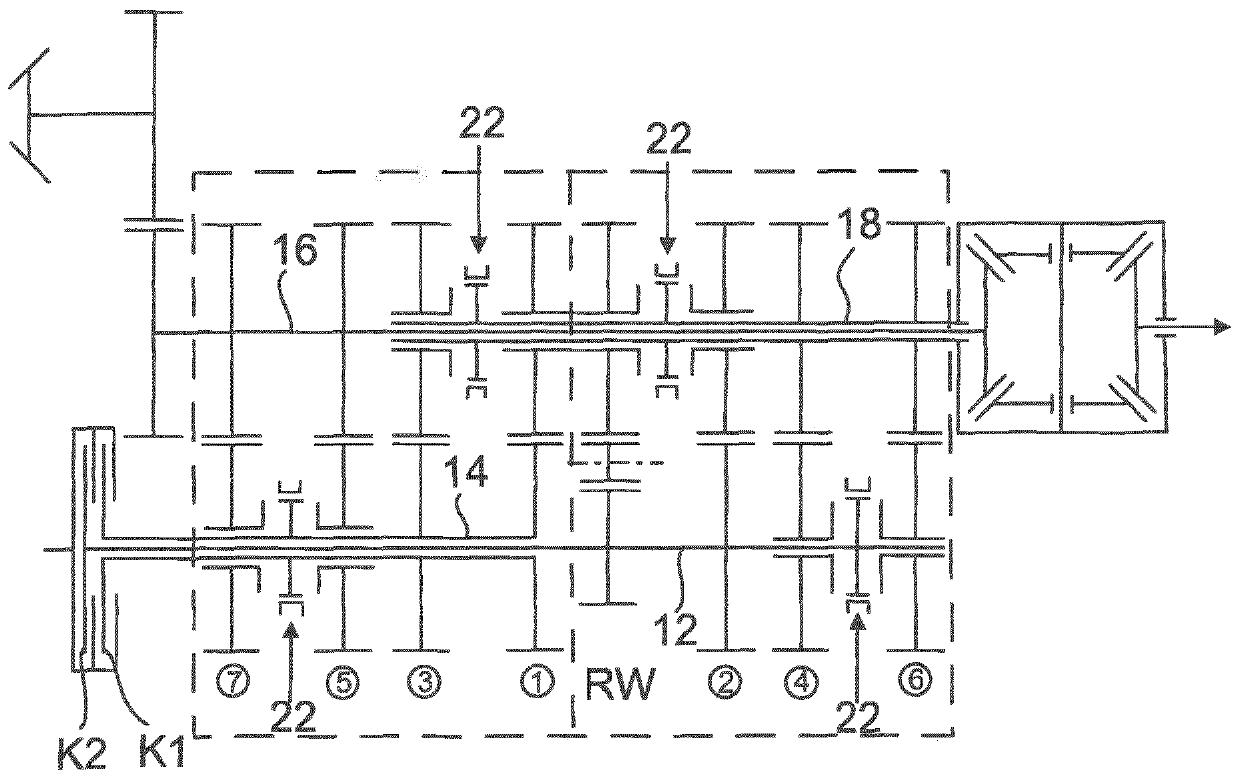
[0028] exist figure 1 A schematic diagram of a dual clutch transmission for a motor vehicle with all-wheel drive is shown in FIG. The dual clutch transmission has seven forward gears (see boxed numbers 1 to 7) and one reverse gear RW. The dual clutch transmission is described below only to the extent necessary to understand the invention. The dual-clutch transmission therefore has two input shafts 12 , 14 which are arranged coaxially with one another and which can be alternately connected to a power source, for example an internal combustion engine, via two hydraulically actuatable multi-plate clutches K1 , K2 . The input shaft 14 is embodied as a hollow shaft, in which the input shaft 12 , which is embodied as a solid shaft, extends. The two input shafts 12 , 14 are driven via gear sets for forward and reverse gears to an output shaft 16 arranged axially parallel and to an intermediate shaft 18 designed as a hollow shaft. The gearsets of the forward gears 1 to 7 each have ...


PUM


Abstract

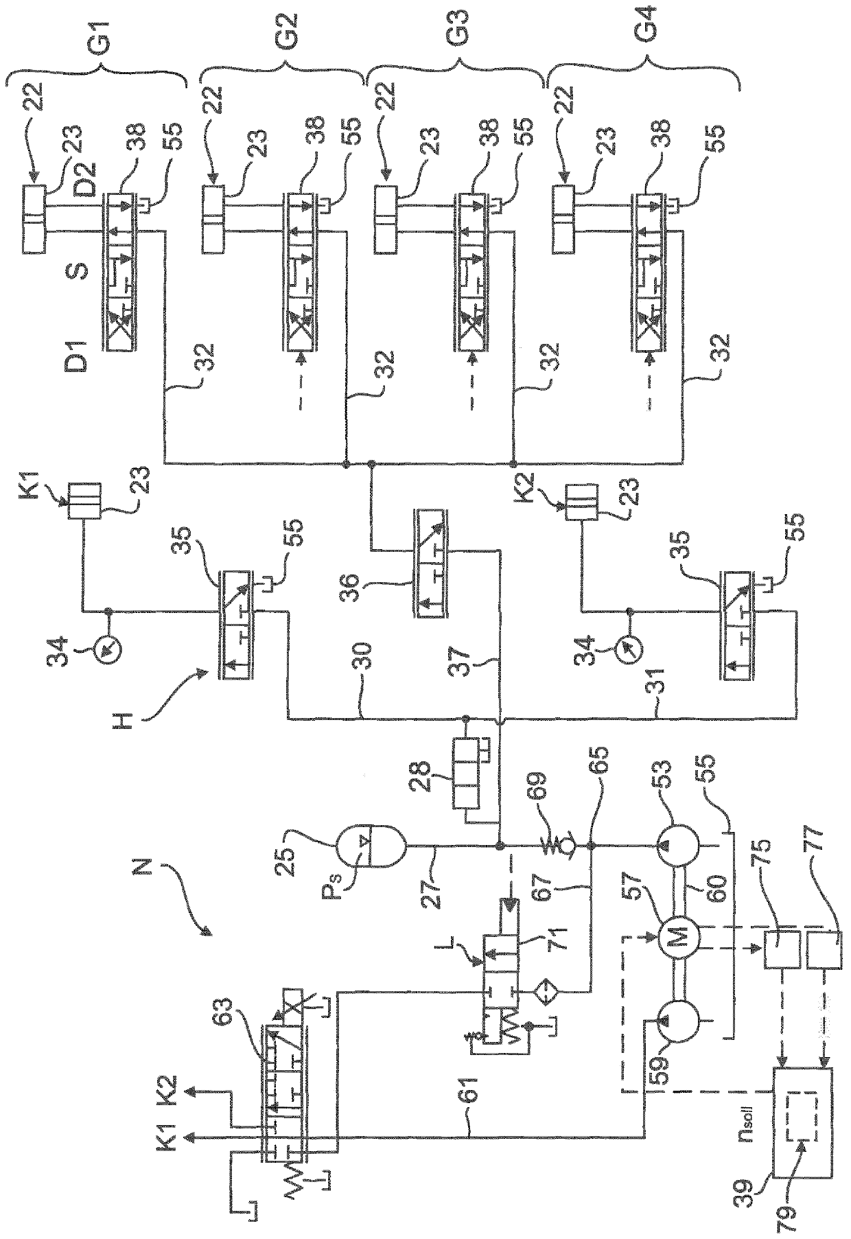
The invention relates to a hydraulic system for an automatic transmission of a motor vehicle, the hydraulic system having a high-pressure circuit (H) in which a pressure accumulator (25), at least one clutch (K1, K2) and a gear are arranged Regulators (G1 to G4) and hydraulic pump (53), which can be actuated by the electronic control unit (39), by means of which the accumulating pressure (p) in the high-pressure circuit (H) can be increased during boost operation S ), wherein a clutch valve (35), which can be actuated by a control unit (39), is arranged in the clutch line (30, 31) between the pressure accumulator (25) and the clutch cylinder (23) of the clutch (K1, K2) , with which the hydraulic pressure present at the clutch hydraulic cylinder ( 23 ) can be regulated, and wherein upstream of the clutch valve ( 25 ) is arranged a safety valve ( 28 ) which can be actuated by the control unit ( 39 ), the safety valve being in the closed position The clutch lines ( 30 , 31 ) are decoupled from the pressure accumulator ( 25 ) in terms of pressure and the accumulated pressure (p S ) loads the clutch lines (30, 31). According to the invention, the control unit (39) has a diagnostic module (79) by means of which a safety valve diagnosis can be performed, in which the safety valve (28) is checked.

Description

technical field [0001] The invention relates to a hydraulic system for an automatic transmission of a motor vehicle, in particular a dual clutch transmission. Background technique [0002] In the case of a dual-clutch transmission, fully automatic gear changes are realized without interruption of traction force by means of two sub-transmissions. The torque is transmitted via one of the two clutches, which connects the two subtransmissions to the drive. The clutches and the gear selectors for engaging gears are actuated by hydraulic cylinders, which can be hydraulically actuated by a hydraulic system. [0003] Document DE 10 2014 003 083 A1 discloses a hydraulic system of this type which has a pressure accumulator for providing an accumulator pressure in the hydraulic system. A control valve actuatable by the electronic control unit is arranged in the clutch line leading from the pressure accumulator to the clutch cylinder, with which control valve the hydraulic pressure pr...

Claims


Application Information

Patent Timeline
Patent Type & Authority Patents(China)
IPC IPC(8): F16H61/12F16H61/688
CPCF16H61/12F16H61/688F16H2059/683F16H2061/1212F16H2061/1264F15B1/04F15B15/20F15B19/005F15B2201/51
Inventor M·威恩哈特
Owner AUDI AG
Learn More