Patch type inductive element and manufacturing method thereof
A technology of inductive components and SMD, which is applied in the field of SMD inductive components and its manufacturing, can solve the problems of low degree of automation and poor product characteristics, and achieve high degree of automation, good electrical consistency and good product characteristics Effect
- Summary
- Abstract
- Description
- Claims
- Application Information
AI Technical Summary
Problems solved by technology
Method used
Image

Examples
Embodiment 1
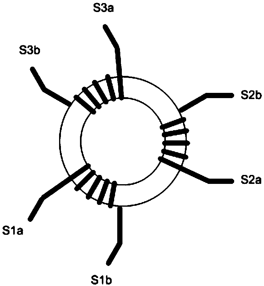
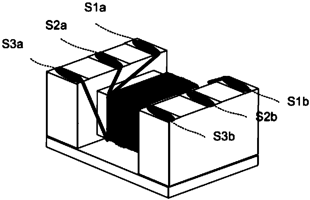
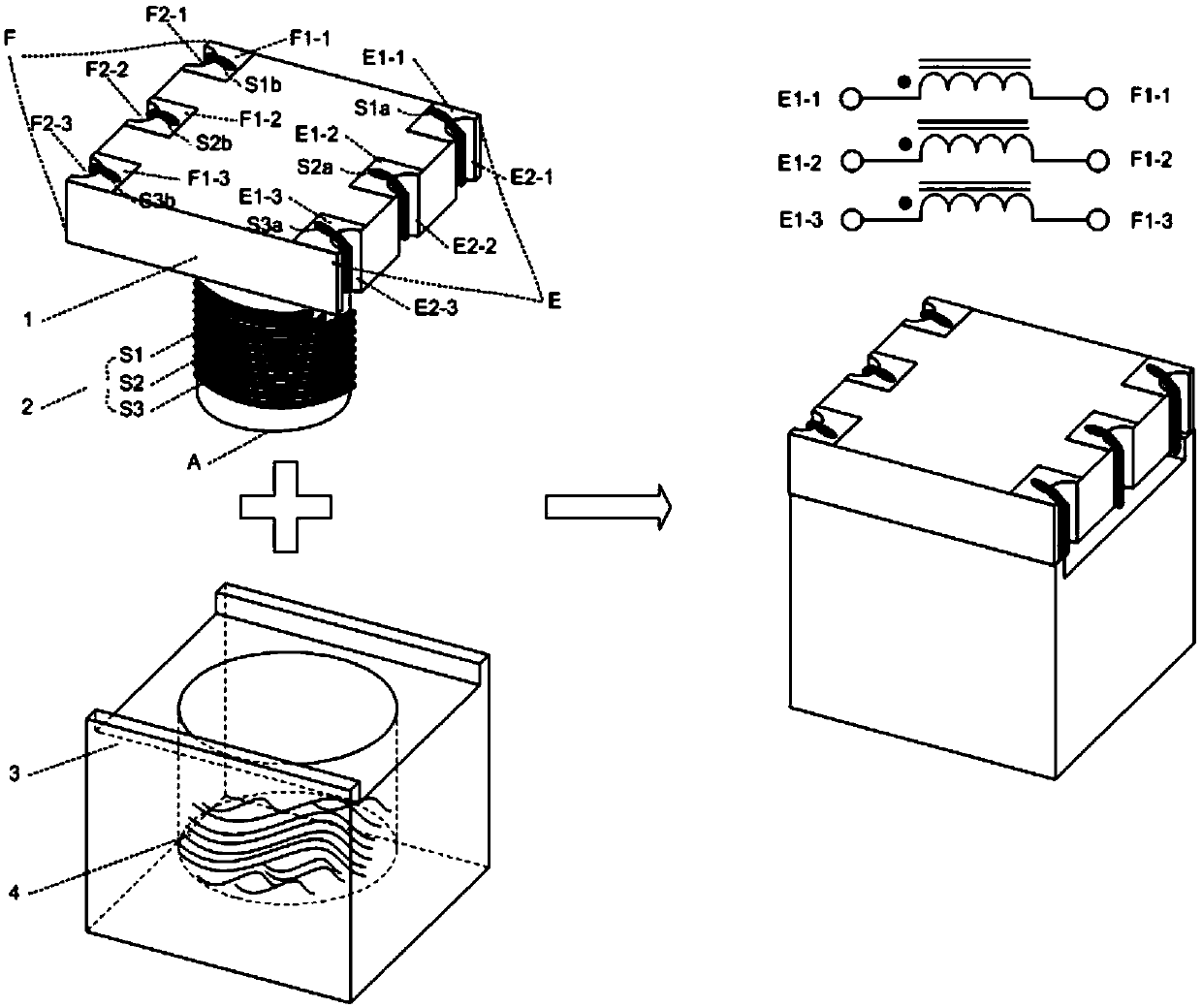
[0042] A chip-type inductive element, including a magnetic core body 1, a coil 2, a magnetic core top cover 3, and an adhesive material 4; it also includes a winding part A on the magnetic core body; a first electrode plate on the magnetic core body E, and the electrodes E1-1, E1-2 and E1-3 on the first electrode plate E of the magnetic core body, and the wire slots E2-1, E2-2 and E2-3 on the first electrode plate E of the magnetic core body ; The second electrode plate F on the magnetic core body, and the electrodes F1-1, F1-2 and F1-3 on the second electrode plate F of the magnetic core body, and the wire hanging groove F2 on the second electrode plate F of the magnetic core body -1, F2-2 and F2-3; wherein, the coil 2 includes three coils S1, S2 and S3.
[0043] refer to figure 2 , first, the starting ends S1a, S2a and S3a of the coils S1, S2 and S3 are respectively hung on the electrodes E1-1, E1-2 and E1-3 on the first electrode plate E, and are connected from the hangin...
Embodiment 2
[0046] A chip-type inductive element, including a magnetic core body 1, a coil 2, a magnetic core top cover 3, and an adhesive material 4; it also includes a winding part A on the magnetic core body; a first electrode plate on the magnetic core body E, and the electrodes E1-1, E1-2 on the first electrode plate E of the magnetic core body, the lead wire groove E2-1 on the first electrode plate F of the magnetic core body; the second electrode plate F on the magnetic core body, and The electrodes F1-1 and F1-2 on the second electrode plate F of the magnetic core body, and the lead groove F2-1 on the second electrode plate F of the magnetic core body; wherein, the coil 2 includes two coils S1 and S2;
[0047] refer to Figure 3a After the starting ends S1a and S2a of the coils S1 and S2 are respectively hung on the electrodes E1-1 and E1-2, the wires come out from the wire hanging groove E2-1 on the corresponding electrode plate, and then the coils S1 and S2 are placed on the win...
Embodiment
[0048] Wherein, in the above-mentioned embodiment, when the coils S1 and S2 are respectively wound with turns N1 and N2 on the winding part A, the coils may be twisted together after the wires come out of the lead slot and then placed on the winding part A. Winding on A, each coil can also be wound on the winding part A separately; in addition, this example does not explain the winding direction, winding sequence and number of turns of the coils S1 and S2 on the winding part A Compared with the ring, this can be set according to actual needs. For further illustration of this embodiment, an example is as follows:
[0049] 1) see Figure 3b After the coils S1 and S2 are hung from the electrodes E1-1 and E1-2 on the first electrode plate E, they go out from the wire slot E2-1 on the first electrode plate E, and the coils S1 and S2 are twisted first. Then wind the same number of turns on the winding part A in the clockwise (or counterclockwise) direction as shown in the figure, a...
PUM
 Abstract
Description
Claims
Application Information
 - R&D
- Intellectual Property
- Life Sciences
- Materials
- Tech Scout
- Unparalleled Data Quality
- Higher Quality Content
- 60% Fewer Hallucinations
Browse by: Latest US Patents, China's latest patents, Technical Efficacy Thesaurus, Application Domain, Technology Topic, Popular Technical Reports.
© 2025 PatSnap. All rights reserved.Legal|Privacy policy|Modern Slavery Act Transparency Statement|Sitemap|About US| Contact US: help@patsnap.com