


Quick Research
Generate reliable direction feasibility study reports for your R&D in just a few steps.

Technical Q&A
Discover and master advanced knowledge NOW. Basics, ideas, possibilities, all at once.

Find Solutions
As an expert in R&D theories, this can generate solutions to your technical problems instantly.

Evaluate Feasibility
Analyze your overall solution with one click, know your potential R&D risks in advance.

Monitor Landscape
Get weekly tech updates, stay abreast of the latest tech innovations and key insights.
Chassis frame of a rail vehicle
A chassis frame and rail vehicle technology, applied in the direction of chassis, bogies, railway car body parts, etc., can solve the problems of lower process reliability, failure to achieve automation, unacceptable process reliability, etc., and achieve reliable anti-rotation Effects of fixing, reducing vibration transmission, and simplifying the joining process
- Summary
- Abstract
- Description
- Claims
- Application Information
AI Technical Summary
Problems solved by technology
Method used
Image


Examples
no. 1 example
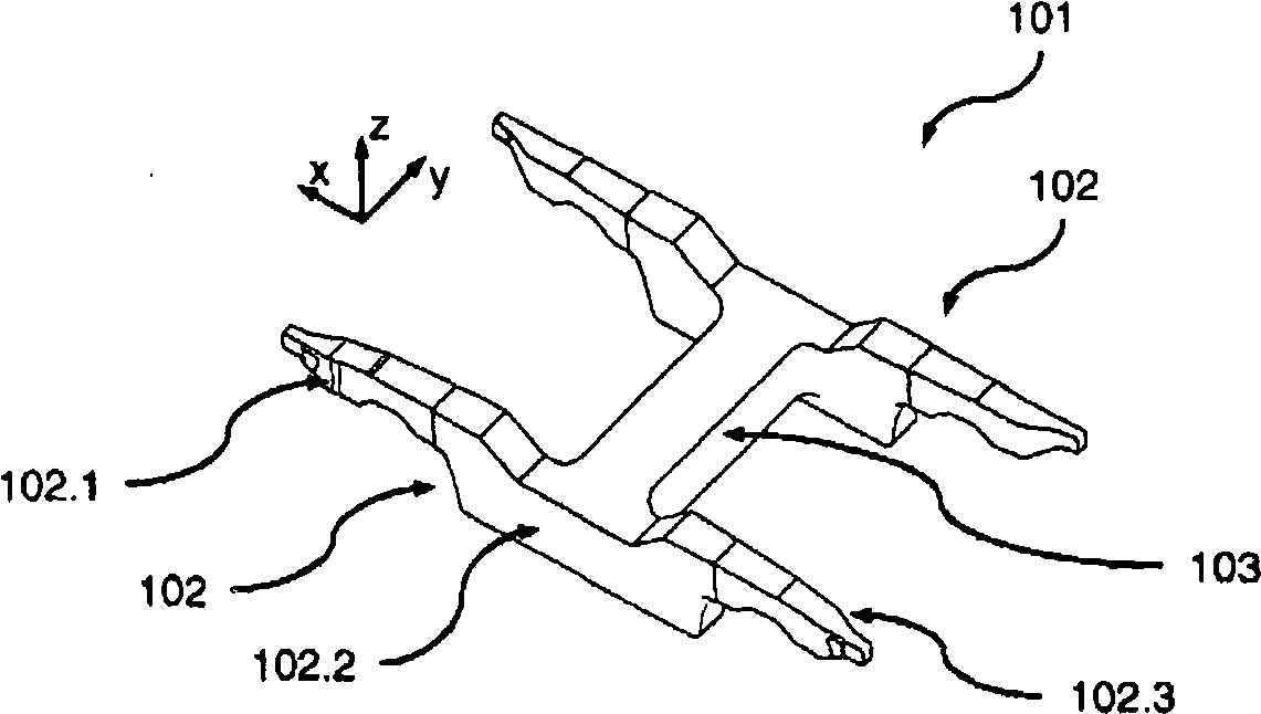
[0059] First refer to the following figure 1 A first preferred embodiment of a chassis frame in the form of a steering wheel frame 101 according to the invention is described. here figure 1 A schematic perspective view of a steering wheel frame 101 is shown, which comprises two substantially parallel lateral longitudinal beams 102 , which are connected to one another via a centrally arranged transverse beam 103 .
[0060]Each stringer 102 comprises a front stringer section 102.1, a middle stringer section 102.2 and a rear stringer section 102.3. In the region of the front side member section 102.1, the rear steering wheel is supported via a not shown main spring on a likewise not shown front wheel unit, for example a front wheel set. In the region of the rear side member section 102.3, the rear steering wheel is supported via a main spring, not shown, on a rear wheel unit, such as a rear wheel set, also not shown.
[0061] The steering wheel frame 101 is produced as a one-p...
no. 2 example
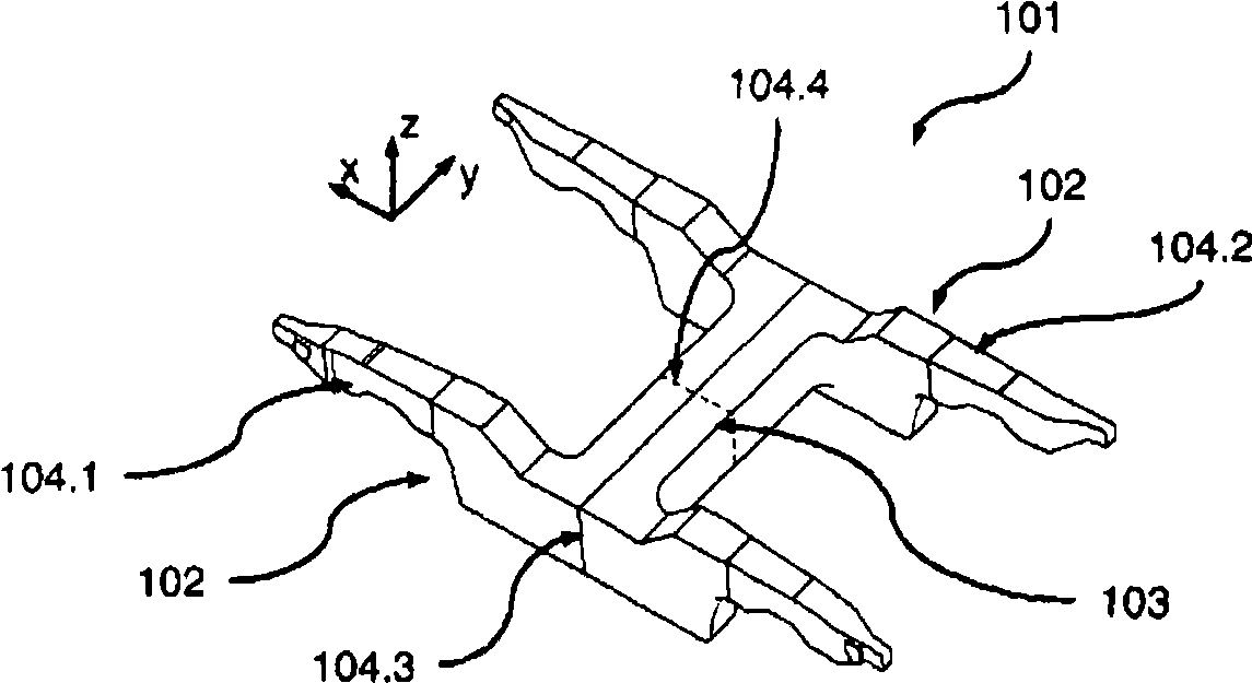
[0063] figure 2 A schematic perspective view of another preferred embodiment of the chassis frame according to the invention is shown, which is a simple variant of the steering wheel frame 101 . The steering wheel frame 101 is here divided into two halves in the form of a front section 104.1 and a rear section 104.2, which are connected to one another in the region of a joint 104.3.
[0064] The front section 104.1 and the rear section 104.2 are designed as identical components made of gray cast iron (GGG40.3 or GJS-400-18U LT), which considerably simplifies their manufacture, since only Make only one basic mold / basic shape. However, it is understood that in other variants of the invention different geometries can also be provided for the two halves.
[0065] The junction extends four times 104.3 centrally through the cross member 103 . The joint points here extend substantially in a joint plane whose surface normal runs parallel to the longitudinal axis (x-axis) of the st...
no. 3 example
[0069] image 3 A schematic perspective view of another preferred embodiment of a chassis frame 201 according to the invention is shown, which has the same external geometry as the steering wheel frame 101 . The steering wheel frame 201 is designed in three parts here, and the two substantially parallel lateral longitudinal beams 202 and the central cross beam 203 connecting the two longitudinal beams are designed to be made of gray cast iron (GGG40.3 or GJS-400-18U LT) composed as separate components.
[0070] The transverse beams 203 are each provided with a lateral projection 203.1 on their upper sides. The corresponding protrusion 203.1 is inserted into a corresponding recess 202.4 in the longitudinal axis 202 from above, ie along the vertical axis (z-axis) of the steering wheel frame 201 . The respective longitudinal beam 202 rests in the direction of the transverse axis (y-axis) of the steering wheel frame 201 against a lateral stop surface 203.2 of the cross beam 203,...
PUM
 Abstract
Description
Claims
Application Information
 - R&D Engineer
- R&D Manager
- IP Professional
- Industry Leading Data Capabilities
- Powerful AI technology
- Patent DNA Extraction
Browse by: Latest US Patents, China's latest patents, Technical Efficacy Thesaurus, Application Domain, Technology Topic, Popular Technical Reports.
© 2024 PatSnap. All rights reserved.Legal|Privacy policy|Modern Slavery Act Transparency Statement|Sitemap|About US| Contact US: help@patsnap.com