
Method for detecting parts of transition section of combustion chamber

A combustion chamber and transition section technology, applied in the direction of measuring devices, mechanical devices, mechanical measuring devices, etc., can solve the problems of narrowing the machining dimension tolerance range of parts in the transition section of the combustion chamber, affecting the feature size of parts, design reference deviation, etc., to achieve The detection results are intuitive, the detection efficiency is improved, and the effect of facilitating production and processing size adjustment and fitter repair

Inactive Publication Date: 2019-04-02
SHENYANG LIMING AERO-ENGINE GROUP CORPORATION
View PDF6 Cites 0 Cited by
  • Summary
  • Abstract
  • Description
  • Claims
  • Application Information

AI Technical Summary

Problems solved by technology

The disadvantage of this detection method is that it narrows the machining dimension tolerance range of parts in the transition section of the combustion chamber, and judges qualified parts as out-of-tolerance parts
This is because the measurement datum established by the three-coordinate CMM inspection is formed according to the end face of the part to be inspected or the inner and outer contours of the end face, which leads to a deviation between the measurement datum of the inspected part and the design datum of the part, which affects the judgment of the feature size of the part

Method used


Image

  • Method for detecting parts of transition section of combustion chamber
  • Method for detecting parts of transition section of combustion chamber
  • Method for detecting parts of transition section of combustion chamber

Examples


Embodiment

[0019] 1) Install the combustion chamber transition section parts on the comprehensive measuring tool:

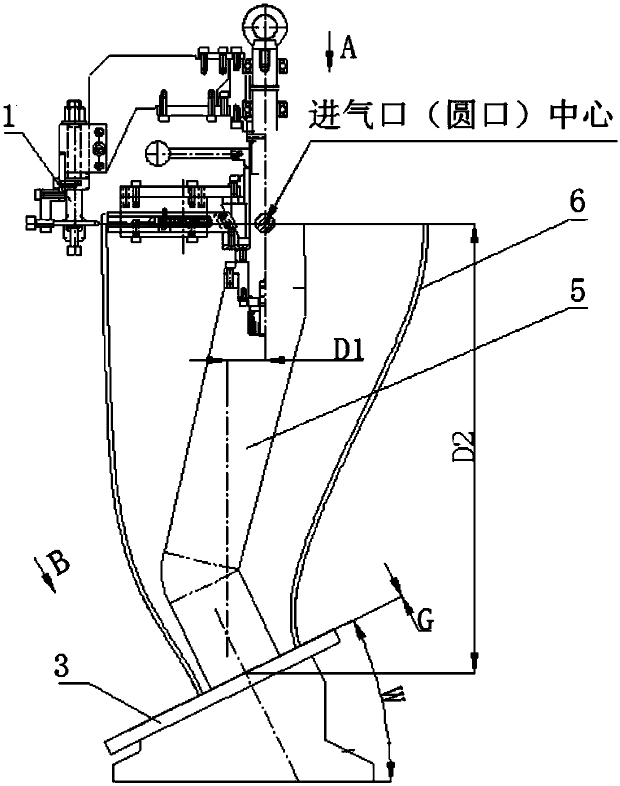
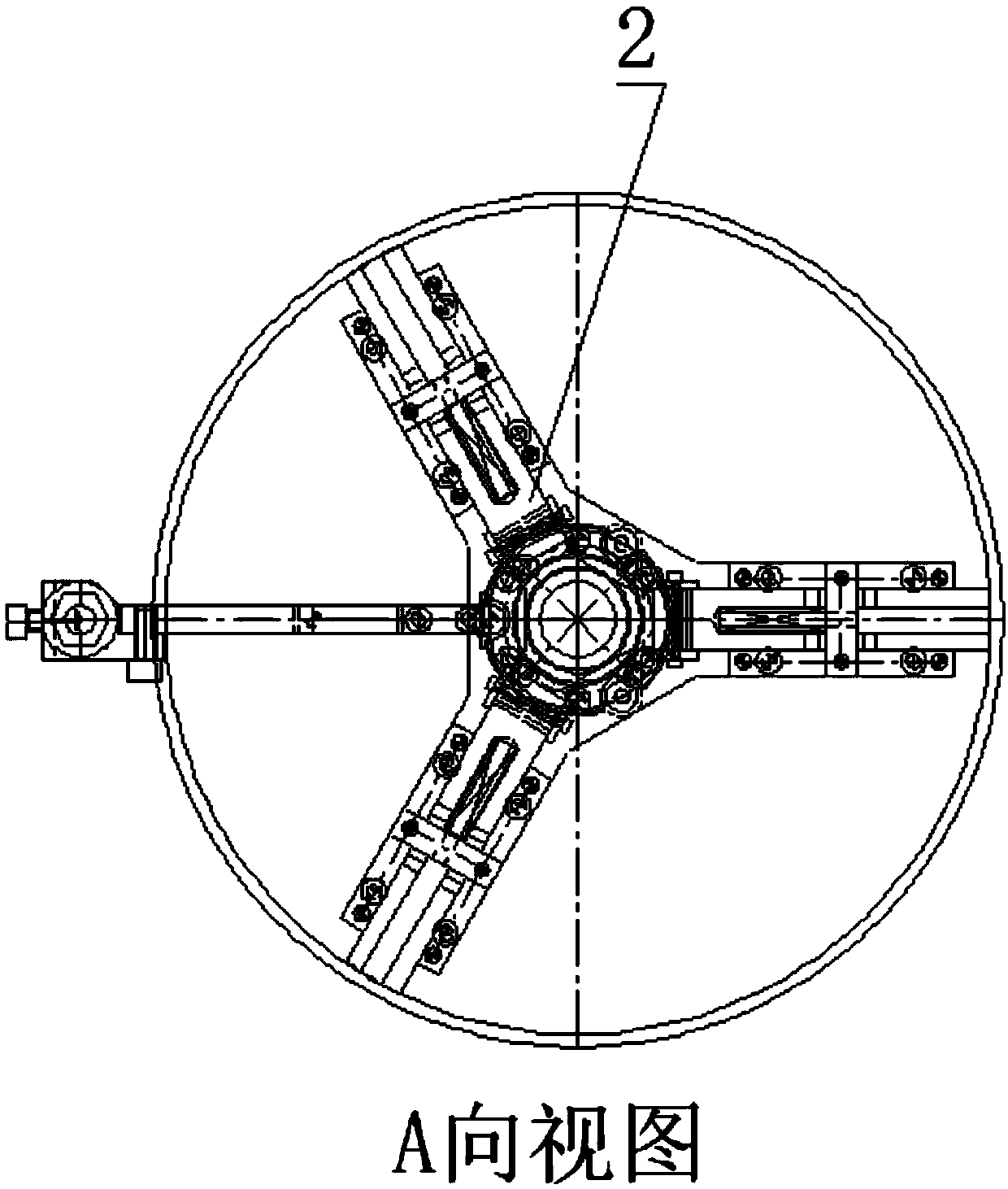
[0020] Lift and remove the tensioning mechanism 2 and the marking mechanism 1 from the column 5, pass the fan-shaped square mouth end of the combustion chamber transition section 6 down through the column 5, place it on the bottom plate 3, and then install the tensioning mechanism. Mechanism 2 and marking mechanism 1 naturally expand and tighten the inner side of the round mouth end of the air inlet of the transition section 6 of the combustion chamber to ensure that the three expansion block support points are in contact with the inner side wall of the round mouth end of the air inlet of the transition section of the combustion chamber.

[0021] 2) Detection of the transition section of the combustion chamber:

[0022] A. Adjust the scale corresponding to the tip of the marking needle on the needle marking mechanism 2 to the minimum value of the length dimension D2 of the ...


PUM


Abstract

The invention discloses a method for detecting parts of a transition section of a combustion chamber, more particularly discloses that a main function of parts of a transition section of a combustionchamber of the heavy-duty gas turbine in the combustion chamber components is the transition. The method comprises the following steps of: transferring the high-temperature gas from an inlet end to anoutlet end through the profile transition to achieve the purpose of rectification; designing and manufacturing an integrated measuring tool to detect the size of the parts of the transition section of the combustion chamber by simulating the assembly state of the parts of the transition section of the combustion chamber; evaluating the size of the parts of the transition section of the combustionchamber by detecting the relative size of the outlet end in the process of detecting only when the air inlet end is fixed. The method for detecting parts of the transition section of the combustion chamber has the advantages of judging the processing quality of the parts of the transition section of the combustion chamber by using the comprehensive measuring tool, avoiding the problem that the coordinate measuring machine narrows the detection tolerance range, and improving the part detecting efficiency. The test results are intuitive and specific, which is convenient for production and processing size adjustment and fitter repair, and provides reference and basis for processing and testing of other similar parts.

Description

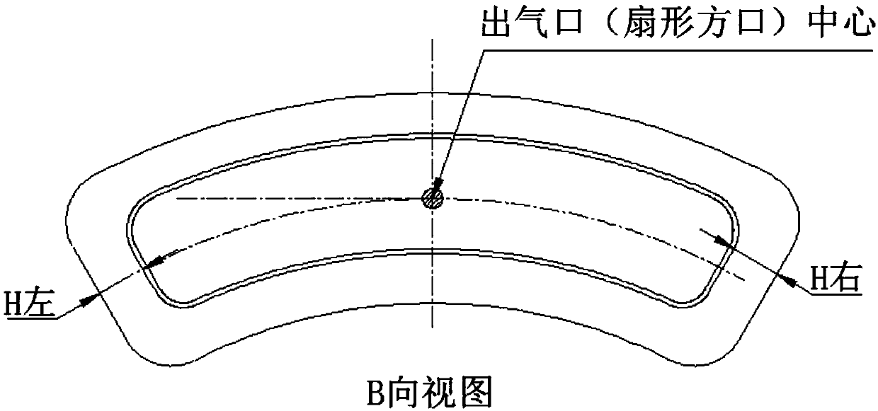
technical field [0001] The invention relates to the field of detecting parts in the transition section of a combustion chamber of a heavy-duty gas turbine, in particular to a method for detecting parts in the transition section of a combustion chamber. Background technique [0002] The transition section of the combustion chamber of heavy-duty gas turbine products is a welded piece of medium-thick plate sheet metal. It has a special-shaped cylinder structure. 13 to 24 sections are smooth. In order to detect the distance between the center of the circular inlet of the transition section and the center of the fan-shaped square of the outlet, the left-right deviation between the center of the fan-shaped square of the outlet and the center of the circular inlet of the inlet, and the flatness of the end face of the fan-shaped square of the outlet , the traditional detection method is to use the three-coordinate CMM to establish a coordinate system according to the requirements o...

Claims


Application Information

Patent Timeline
Patent Type & Authority Applications(China)
IPC IPC(8): G01B5/00G01B5/02G01B5/14G01B5/252
CPCG01B5/003G01B5/02G01B5/14G01B5/252
Inventor 杨海钢杨树余李塞川赵宝群
Owner SHENYANG LIMING AERO-ENGINE GROUP CORPORATION
Learn More