
Plate edge milling machine

A technology of edge milling machine and plate, applied in the direction of milling machine equipment, milling machine equipment details, metal processing machinery parts, etc., can solve the problems of unguaranteed work quality, low processing efficiency, high energy consumption, etc.

Inactive Publication Date: 2019-04-02
太仓松立五金制品有限公司
View PDF0 Cites 1 Cited by
  • Summary
  • Abstract
  • Description
  • Claims
  • Application Information

AI Technical Summary

Problems solved by technology

[0002] With the rapid development and construction of cities, the demand for various furniture and decoration materials continues to increase, and the demand for various panels also increases sharply. The panels are processed into various building materials, furniture or floors; edge milling machine is a kind of Using the working principle of high-speed milling of the cutter head, it is specially used as a welding auxiliary equipment for opening the weld bevel of the steel plate before welding. , widely used in boiler, pressure vessel manufacturing industry, shipbuilding, electric power, petroleum, chemical machinery, engineering machinery manufacturing, can process all kinds of low carbon steel plate, stainless steel plate and aluminum plate before welding beveled edge, straight edge, U-shaped slope Most of the current edge milling machines fix the plate on the workbench, and the workbench and the milling mechanism move relatively, and drive the plate to contact with the edge milling machine to perform edge milling on the plate, or manually push the plate to move, so that The edge milling machine is in contact with the plate and processes the plate. These edge milling machines have a simple structure, but the processing efficiency is low, the safety is poor, and the energy consumption is high, and the work quality cannot be guaranteed, and the work efficiency is low and the labor intensity is high.

Method used


Image

  • Plate edge milling machine
  • Plate edge milling machine
  • Plate edge milling machine

Examples


Embodiment Construction

[0012] Embodiments of the present invention are described in detail below, examples of which are shown in the drawings, wherein the same or similar reference numerals designate the same or similar elements or elements having the same or similar functions throughout. The embodiments described below by referring to the figures are exemplary only for explaining the present invention and should not be construed as limiting the present invention.

[0013] In the description of the present invention, unless otherwise specified and limited, it should be noted that the terms "installation", "connection" and "connection" should be understood in a broad sense, for example, it can be mechanical connection or electrical connection, or two The internal communication of a component can be directly connected or indirectly connected through an intermediary. Those of ordinary skill in the art can understand the specific meanings of the above terms according to specific situations.

[0014] Re...


PUM


Abstract

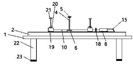
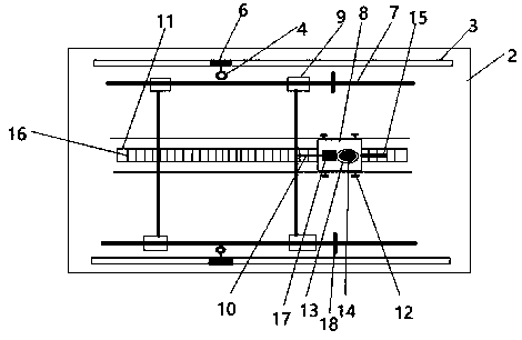
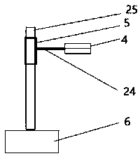
The invention discloses a plate edge milling machine. The front side and the back side of the upper surface of a workbench are provided with guide rails, the two guide rails are each provided with a milling cutter mechanism capable of sliding left and right along the corresponding guide rail, each milling cutter mechanism is arranged on a lifting rod, therefore, the positions of the milling cuttermechanisms can be set according to the stroke of a plate and concrete data needed for machining, and the height of milling cutters can be adjusted according to the height of the plate; two slide rails are arranged on the portions, on the inner sides of the guide rails, of the workbench, and a plate clamping mechanism is arranged on the slide rails; and the plate clamping mechanism particularly comprises a tractor vehicle and four air cylinder clamping devices, every two air cylinder clamping devices are set as a group, each group is arranged on the corresponding slide rail, and the two groupsof air cylinder clamping devices are fixedly connected and slide on the slide rails in the same movement track.

Description

technical field [0001] The invention relates to the field of mechanical processing, in particular to a plate edge milling machine. Background technique [0002] With the rapid development and construction of the city, the demand for various furniture and decoration materials continues to increase, and the demand for various panels also increases sharply. The panels are processed into various building materials, furniture or floors; edge milling machine is a kind of Using the working principle of high-speed milling of the cutter head, it is specially used as a welding auxiliary equipment for opening the weld bevel of the steel plate before welding. It is mainly divided into automatic walking plate edge milling machine, large-scale edge milling machine, CNC plate edge milling machine, etc , Widely used in boiler, pressure vessel manufacturing industry, shipbuilding, electric power, petroleum, chemical machinery, engineering machinery manufacturing, can process all kinds of low...

Claims


Application Information

Patent Timeline
Patent Type & Authority Applications(China)
IPC IPC(8): B23C3/12B23Q3/08B23Q7/08
CPCB23C3/12B23Q3/08B23Q7/08
Inventor 周锡君
Owner 太仓松立五金制品有限公司
Learn More