
High-speed coiled material powder spray device, working method thereof and power spray production line

A technology of spraying device and powder coating, applied in spraying device, electrostatic spraying device, device for coating liquid on the surface, etc., can solve the problems of not getting good results and technical limitations, so as to improve the powdering effect and reduce the The effect of relative motion speed

Pending Publication Date: 2019-04-02
江苏变色龙微粉技术有限公司
View PDF0 Cites 5 Cited by
  • Summary
  • Abstract
  • Description
  • Claims
  • Application Information

AI Technical Summary

Problems solved by technology

For decades, the research and development of coil coating using powder coatings has been going on, but due to technical limitations, the oil-to-powder conversion of coil coating has not achieved good results

Method used

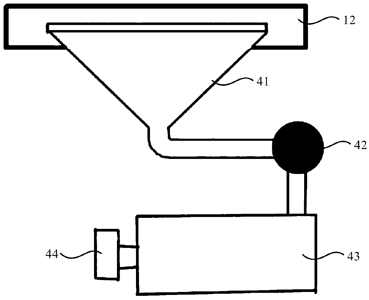

Image

  • High-speed coiled material powder spray device, working method thereof and power spray production line
  • High-speed coiled material powder spray device, working method thereof and power spray production line
  • High-speed coiled material powder spray device, working method thereof and power spray production line

Examples


Embodiment 1

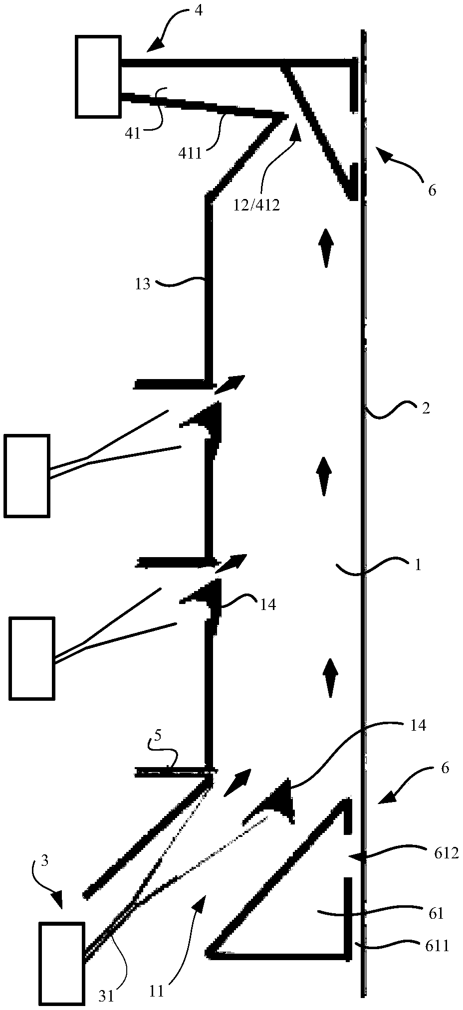
[0025] figure 1 It is a structural schematic diagram of the powder spraying device of the present invention.

[0026] Such as figure 1 As shown, the present embodiment 1 provides a powder spraying device, comprising: a powder spraying chamber 1 equipped with high-voltage static electricity; 2 moving in the same direction; and the powder spray chamber 1 is suitable for forming a corona space, so that the powder coating can be electrostatically adsorbed on the surface of the workpiece.

[0027] Optionally, the workpiece can be but not limited to color steel coils and color aluminum coils, and can be continuously conveyed through a conveying line.

[0028] Preferably, the movement speed of the powder coating and the workpiece can be kept in the same direction by controlling the air velocity.

[0029] Experiments have found that powder electrostatic spraying can be applied normally at a slow speed, but it is difficult for the powder to be efficiently adsorbed to the substrate a...

Embodiment 2

[0054] On the basis of Example 1, this Example 2 provides a working method of a powder coating device, the powder coating device is suitable for driving the powder coating and the moving workpiece to move in the same direction through the air flow, and the powder coating is adsorbed by static electricity on the workpiece surface.

[0055] For the specific structure and implementation process of the powder spraying device, please refer to the relevant discussion of Embodiment 1, and details will not be repeated here.

Embodiment 3

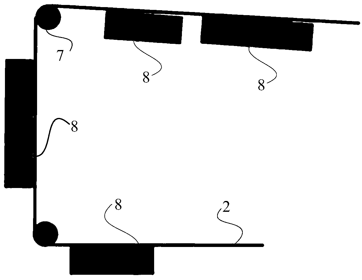
[0057] image 3 It is a structural schematic diagram of the powder spraying production line of the present invention.

[0058] On the basis of Example 1, such as image 3 As shown, the present embodiment 3 provides a powder coating production line, including: a conveyor line 7 for transporting workpieces 2 and several powder coating devices 8 as described above; The side of the line 7 is used to powder coat the moving workpiece 2 respectively.

[0059] Optionally, the workpiece may be, but not limited to, continuous workpieces such as color steel coils and color aluminum coils conveyed by a conveyor line. Each powder coating device can be installed on both sides of the workpiece to perform powder coating on both sides. When the sprayed surface of the workpiece needs to be sprayed in multiple layers (for example, primer and flour need to be coated), multiple powder spraying devices can be installed on the side of the sprayed surface of the workpiece along the moving directio...


PUM


Abstract

The invention belongs to the technical field of coating equipment and particularly relates to a high-speed coiled material powder spray device, a working method thereof, a power spray production lineand a power spray line applicable to rapid color change. The powder spray device comprises a power spray cavity with high-pressure static electricity. The power spray cavity is suitable for allowing airflow to pass through so that powder coating in the power spray cavity can be driven to move in the same direction as a moving workpiece. A corona space is suitable for being form in the power spraycavity so that the powder coating can adsorb to the surface of the workpiece through static electricity. By means of the powder spray device, the relative movement speed of the power coating and the workpiece is reduced; then, the powder coating is sprayed to the surface of the workpiece through the static electricity; the phenomenon that adsorption of the powder coating is influenced when the moving speed of the workpiece is high is avoided; and the powder application effect of the workpiece is improved.

Description

technical field [0001] The invention relates to the technical field of coating equipment, in particular to a high-speed coil powder coating device and its working method, a powder coating production line and a powder coating line suitable for rapid color change. Background technique [0002] Coil powder coating mainly refers to the coating of color steel plate and color aluminum plate. It is to uniformly coat the paint on one or both sides of the unrolled flat strip on the continuous coating production line running at high speed. , and quickly bake and solidify, and then go through cooling and winding processes to complete the coating. Coil coating is characterized by fast and high efficiency, flat and uniform coating and thin coating, low production cost and large output. The coating of color steel plate is the largest number of coating applications in coil coating, followed by the coating of color aluminum plate. The line speed of color steel plate coating is usually 60-...

Claims


Application Information

Patent Timeline
IPC IPC(8): B05B5/08B05B5/16B05B14/45B05B14/48B05D1/06
CPCB05B5/081B05B5/1683B05B14/45B05B14/48B05D1/06Y02P70/10
Inventor 郭黎晓郭亦之池建成巴图李松峰张云峰
Owner 江苏变色龙微粉技术有限公司
Learn More