Controller Design Method for Ducted Multi-rotor Tethered UAV
A design method and ducted technology, applied in three-dimensional position/channel control, attitude control, control/regulation system, etc., can solve the problem of insufficient control parameter optimization, poor control ability of UAV controller, weak anti-interference ability, etc. problems, to achieve the effect of efficient use of energy, long-term flight, and atmospheric lift
- Summary
- Abstract
- Description
- Claims
- Application Information
AI Technical Summary
Problems solved by technology
Method used
Image
Examples
specific Embodiment approach 1
[0030] The controller design method of the ducted multi-rotor moored UAV of the present embodiment, the design method is realized through the following steps:
[0031] Step 1, adopt the analysis method of finite element, analyze the general structure aerodynamic characteristic parameter of duct type multi-rotor moored UAV, parameter comprises: determine the aerodynamic characteristic parameter of rotor, duct and deflector vane,
[0032] Maximize the efficiency of the ducted rotor under the same voltage and current, complete the overall design of the ducted multi-rotor tethered UAV; and select the appropriate power device and electronic equipment to complete the hardware of the ducted multi-rotor tethered UAV System design; then select tethered cables with light unit weight, tensile strength, high voltage resistance, low resistance, and strong environmental adaptability to complete the design of the tethered power supply system to achieve long-term uninterrupted flight;
[0033...
specific Embodiment approach 2
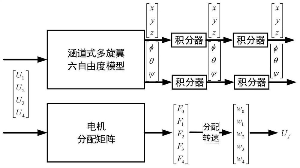
[0039] Different from the specific embodiment one, the controller design method of the ducted multi-rotor tethered UAV in this embodiment, the dynamic model of the body of the ducted multi-rotor tethered UAV as described in step 2 The process is that the body of the ducted multi-rotor tethered UAV is referred to as the body for short.
[0040] Step 21. Let Xb, Yb, and Zb be the roll axis, pitch axis, and yaw axis of the ducted multi-rotor tethered UAV, respectively, and the corresponding attitude angle is defined as:
[0041] Roll angle φ (roll): the angle between the body axis Zb and the vertical plane of the earth passing through the body axis Xb, and rolling clockwise along the positive direction of Xb is positive;
[0042] Pitch angle θ (pitch): the angle between the rolling axis Xb and the ground level, and the clockwise deflection along the Yb positive direction is positive;
[0043] Yaw angle ψ(yaw): the angle between the projection of the rolling axis Xb on the earth ...
specific Embodiment approach 3
[0101] Different from the second specific embodiment, the controller design method of the ducted multi-rotor tethered UAV in this embodiment, the process of obtaining the assigned value of each motor pulling force control described in step 2 is that the ducted multi-rotor The rotor tethered UAV has 4 control channels and 1 motor. The specific distribution value of the motor cannot be obtained through 4 equations, and the solution can only be solved by introducing conditional equations reasonably. Order F 1 +F 3 =F 2 +F 4 , combined with the following equation:
[0102]
[0103] It can be solved to obtain the values of F0, F1, F2, F3, and F4:
[0104]
[0105] In the formula, A represents the distribution matrix of the motor; through the four control variables, the value of the pulling force of the five motors can be obtained, and then the speed of the motor can be controlled.
PUM
 Abstract
Description
Claims
Application Information
 - R&D
- Intellectual Property
- Life Sciences
- Materials
- Tech Scout
- Unparalleled Data Quality
- Higher Quality Content
- 60% Fewer Hallucinations
Browse by: Latest US Patents, China's latest patents, Technical Efficacy Thesaurus, Application Domain, Technology Topic, Popular Technical Reports.
© 2025 PatSnap. All rights reserved.Legal|Privacy policy|Modern Slavery Act Transparency Statement|Sitemap|About US| Contact US: help@patsnap.com


