
A high-speed non-coherent communication ranging device and method

A technology of distance measuring device and distance measuring method, which is applied in the direction of measuring device, radio wave measurement system, instrument, etc., can solve the problems of consuming large system internal resources, unable to meet normal communication and high-precision distance measurement, etc., and achieve adaptive communication speed Wide range, avoiding the decrease of ranging accuracy, and improving the effect of ranging accuracy

Active Publication Date: 2022-03-22
HUNAN MAXWELL ELECTRONICS TECH
View PDF9 Cites 0 Cited by
  • Summary
  • Abstract
  • Description
  • Claims
  • Application Information

AI Technical Summary

Problems solved by technology

The existing information frame ranging method is mainly based on a fixed local clock. In the existing information frame ranging, a special ranging frame is set in the communication data frame, and the distance is measured by comparing the local fixed clock with the recovered clock. The clock is tens of In order to complete such a large number of clock comparisons, it takes a lot of internal system resources. When the system communication rate is increased to the order of magnitude (hundreds of Mbps to several Gbps), the local clock signal recovery at the receiving end will be more The logical computing resources cannot meet the requirements of normal communication and high-precision ranging in the high-speed range

Method used


Image

  • A high-speed non-coherent communication ranging device and method
  • A high-speed non-coherent communication ranging device and method

Examples


Embodiment Construction

[0036] In order to describe the technical content, achieved goals and effects of the present invention in detail, the following descriptions will be made in conjunction with the embodiments and accompanying drawings.

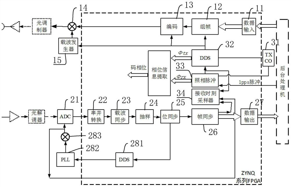
[0037] Such as figure 1 Shown is a high-speed non-coherent communication ranging device of the present invention, including: a transmitting unit, a receiving unit and a clock phase acquisition module;

[0038] The transmitting unit includes a transmission processing module, an optical modulation module and an optical transmitter. The transmission processing module is used to frame, encode, and load the transmitted data to the optical modulation module, and the optical modulation module converts it into laser emission through the optical transmitter. go out;

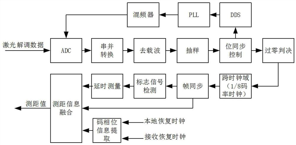
[0039] The receiving unit includes a receiving processing module, an optical demodulator and an optical receiver. The optical demodulator receives the laser signal sent back by the satellite through the op...


PUM


Abstract

The invention discloses a high-speed non-coherent communication ranging device and method, including a transmitting unit, a receiving unit and a clock phase acquisition module; the transmitting unit includes a sending processing module, an optical modulation module and an optical transmitter, and the sending processing module is used for sending data After framing, encoding, and carrier loading processing, the optical modulation module converts it into laser light and emits it through the optical transmitter; the receiving unit includes a receiving processing module, an optical demodulator and an optical receiver, and the receiving processing module is used to receive the output of the optical demodulator. Data, demodulates the received data, restores the required received data after decoding and decoding, and obtains the recovered clock information from the demodulated ADC dynamic sampling clock signal; the clock phase acquisition module, the clock phase acquisition module and the transmission processing module connected, and the clock phase acquisition module is connected to the receiving processing module. The invention can simultaneously realize high-speed communication and high-precision ranging device, and meanwhile, the device has small volume and low power consumption.

Description

technical field [0001] The invention relates to the field of laser communication ranging, in particular to a high-speed non-coherent communication ranging device and method. Background technique [0002] The existing commonly used ranging methods include side tone ranging, pseudo code ranging, sound code mixed ranging, information frame ranging, etc. Generally, the ranging data is obtained by measuring the two-way signal transmission delay. The information frame ranging method belongs to non-coherent ranging and can be applied to two-way ranging and time synchronization (Two-Way Ranging and Time Transmit, TWRTT) technology; compared with other ranging methods, this method can realize high-speed communication (Hundreds of Mbps to several Gbps level) to complete ranging at the same time, especially suitable for satellite-ground and inter-satellite high-speed communication links. The existing information frame ranging method is mainly based on a fixed local clock. In the exist...

Claims


Application Information

Patent Timeline
Patent Type & Authority Patents(China)
IPC IPC(8): G01S17/08
CPCG01S17/08
Inventor 龚高茂张传胜
Owner HUNAN MAXWELL ELECTRONICS TECH
Learn More