
Conical ray-based X-CT detection device

A technology of X-CT and detection equipment, applied in the direction of measuring devices, material analysis using wave/particle radiation, instruments, etc., can solve research bottlenecks, detection equipment cannot accurately measure data information, and spatial resolution data acquisition time Short-ray utilization efficiency and other issues to achieve the effect of eliminating errors, ensuring integrity and accuracy, and excellent adaptability

Inactive Publication Date: 2019-03-29
王迅
View PDF0 Cites 1 Cited by
  • Summary
  • Abstract
  • Description
  • Claims
  • Application Information

AI Technical Summary

Problems solved by technology

Compared with other geometric structures, the cone beam CT system has high spatial resolution, short data acquisition time, and high ray utilization efficiency. The current cone beam CT system mainly has two geometric structures. One scanning ray beam is a complete cone beam, using the standard cone beam reconstruction algorithm; the other scanning ray beam is a half cone beam, using a modified reconstruction algorithm, this structure is mainly used in emerging mammary gland inspection systems, with the continuous development of image computing technology In-depth, human body materials and other testing equipment using this technology are constantly being developed. At present, due to the multi-layer and multi-faceted testing of materials in material testing equipment, current testing equipment often cannot accurately measure data information. Related research on materials brings Come to a certain bottleneck,

Method used


Image

  • Conical ray-based X-CT detection device
  • Conical ray-based X-CT detection device

Examples


Embodiment Construction

[0020] The present invention will be further described in detail below in conjunction with the accompanying drawings and examples. The following examples are explanations of the present invention and the present invention is not limited to the following examples.

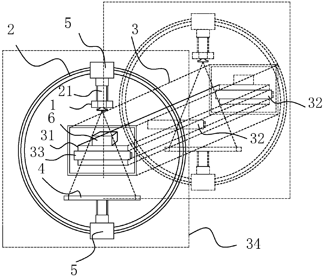
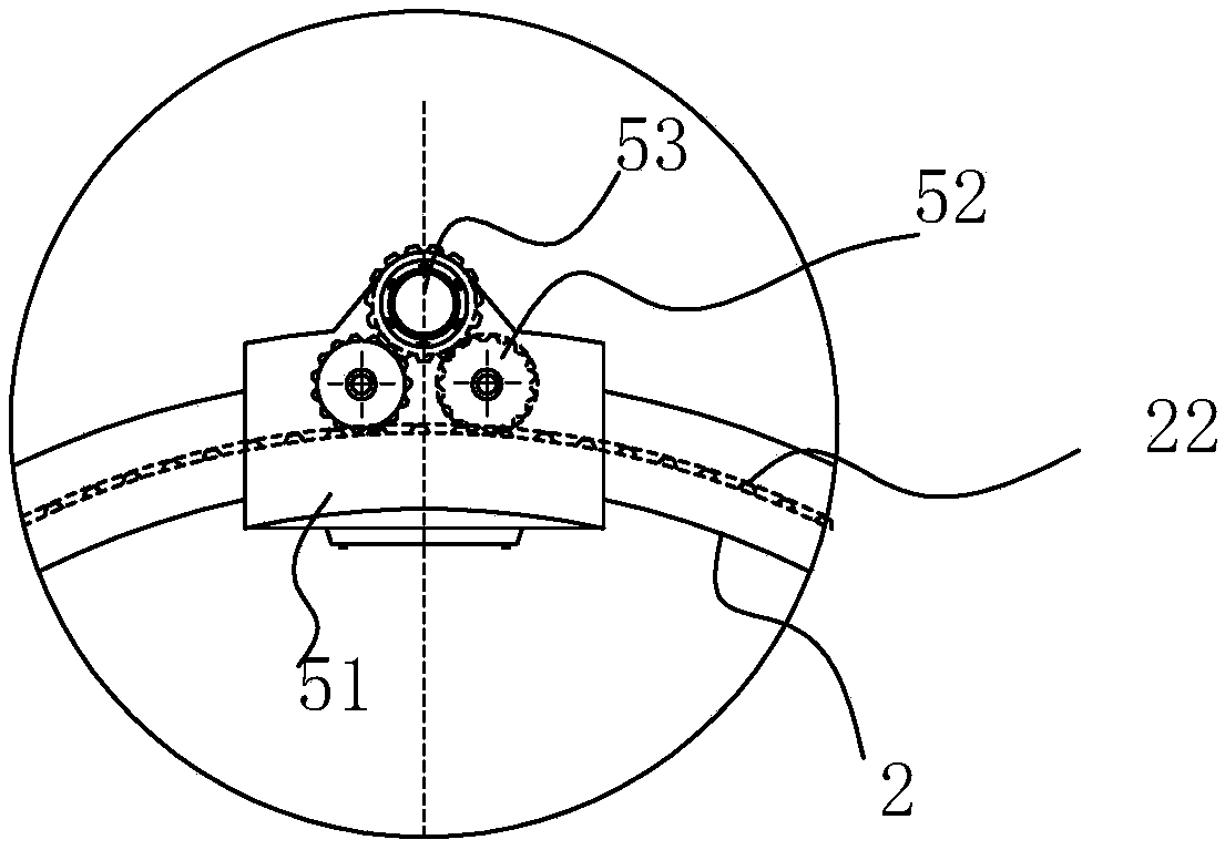
[0021] see Figure 1-Figure 2 , the present embodiment is an X-CT detection device based on cone rays, characterized in that it includes a transmitter 1, a walking frame 2, a detection support platform 3 and a flat panel detector 4, and the walking frame 2 is ring-shaped, and the The walking frame 2 described above is provided with a walking track for cooperating with the walking trolley 5, and the transmitter 1 and the flat panel detector 4 are all fixed on the corresponding walking trolley 5, and the transmitter 1 and the flat panel detector 4 are arranged on the walking frame. 2 The opposite position is set on the same radial line of the walking frame 2, the detection support platform 3 is set in the middle of th...


PUM


Abstract

The invention discloses a conical ray-based X-CT detection device. The device is characterized by comprising a transmitter, a walking frame, a detection supporting platform and a flat panel detector;the walking frame is in an annular shape; the walking frame is provided with a walking track used for being matched with a walking trolley in walk; the transmitter and the flat panel detector are bothfixed on the corresponding walking trolley; and the transmitter and the flat panel detector are arranged in the opposite positions of the walking frame, namely, on the same radial line of the walkingframe. The device is reasonable in structural design; image scanning and processing can be carried out on materials effectively by utilizing a conical ray-based CT technology; more accurate internalstructure details of the materials are effectively provided; the device has an important significance for the research of the materials; and the device can be used for scanning the materials which canmove in multiple directions (axial and radial directions) to obtain all-directional data.

Description

technical field [0001] The invention relates to an X-CT detection device based on cone rays. Background technique [0002] X-CT is X-ray computerized tomography. It uses precisely collimated X-ray beams and highly sensitive detectors to perform cross-sectional scans around the affected parts one by one. It has the characteristics of fast scanning time and clear images. At present, CT detection is widely used in many fields such as medicine, industry, and materials. [0003] In recent years, cone-beam CT using area array detectors has gradually entered the practical stage. Compared with other geometric structures, the cone beam CT system has high spatial resolution, short data acquisition time, and high ray utilization efficiency. The current cone beam CT system mainly has two geometric structures. One scanning ray beam is a complete cone beam, using the standard cone beam reconstruction algorithm; the other scanning ray beam is a half cone beam, using a modified reconstruc...

Claims


Application Information

Patent Timeline
Patent Type & Authority Applications(China)
IPC IPC(8): G01N23/046
CPCG01N23/046G01N2223/03G01N2223/1016G01N2223/401
Inventor 王迅
Owner 王迅
Learn More