


Quick Research
Generate reliable direction feasibility study reports for your R&D in just a few steps.

Technical Q&A
Discover and master advanced knowledge NOW. Basics, ideas, possibilities, all at once.

Find Solutions
As an expert in R&D theories, this can generate solutions to your technical problems instantly.

Evaluate Feasibility
Analyze your overall solution with one click, know your potential R&D risks in advance.

Monitor Landscape
Get weekly tech updates, stay abreast of the latest tech innovations and key insights.
Multifunctional closestool
A toilet and multi-functional technology, applied in the field of toilet structure, can solve the problems such as defects in the use of keys, and achieve the effects of simple control, energy saving, reasonable and compact structure design, and convenience for defecation
- Summary
- Abstract
- Description
- Claims
- Application Information
AI Technical Summary
Problems solved by technology
Method used
Image

Examples
Embodiment 1
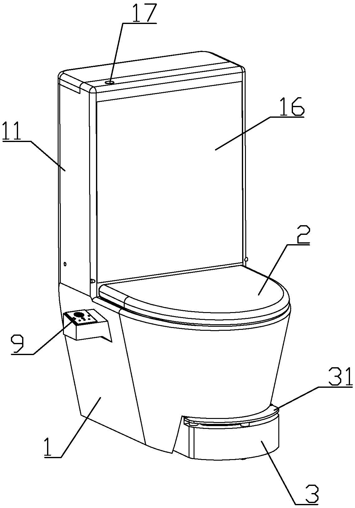
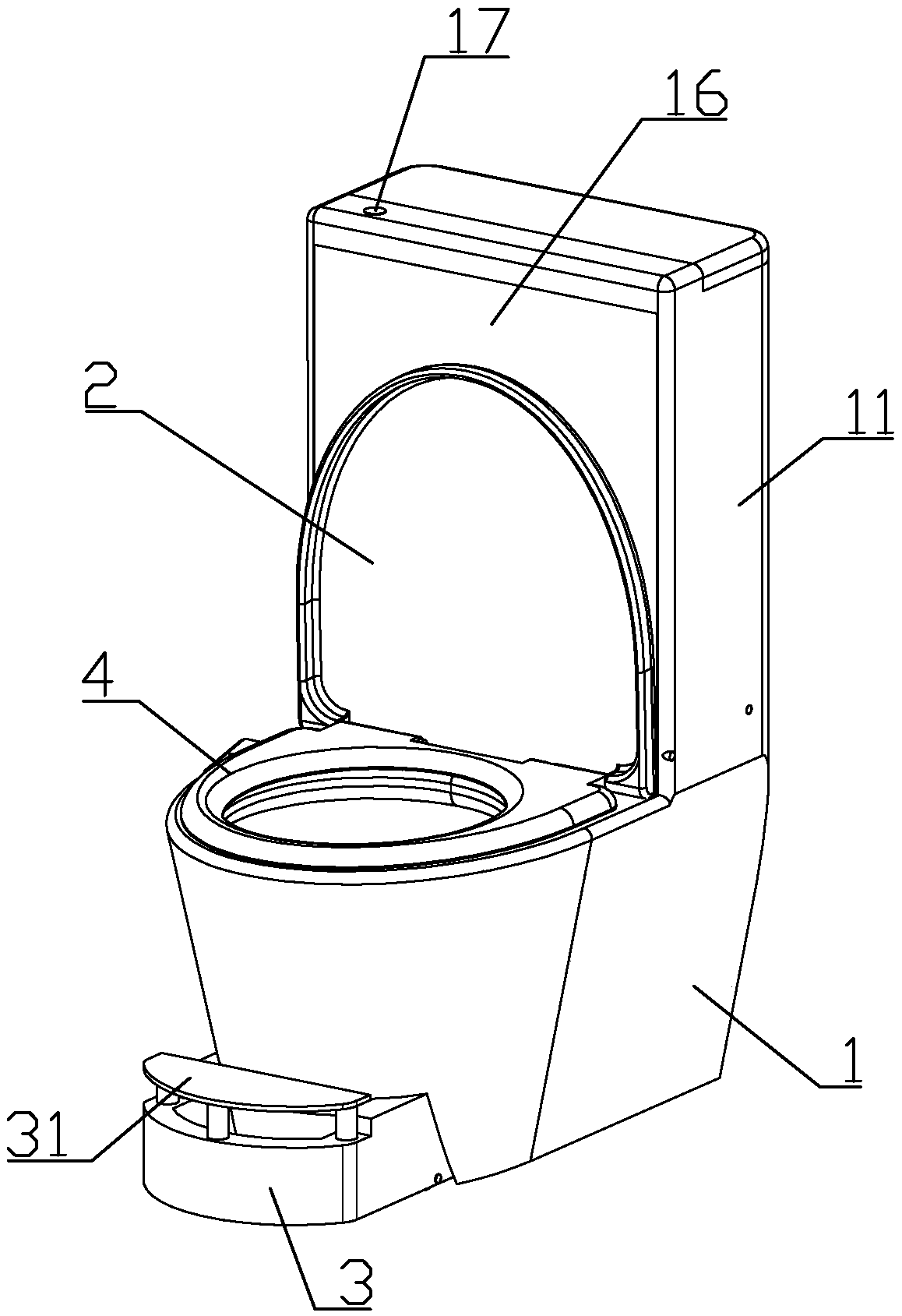
[0081] combine Figure 1 to Figure 7 As shown, this embodiment provides a multifunctional toilet, including a toilet body 1, the rear side of the toilet body is a water storage tank part 11; and toilet seat 2. The toilet body is integrally formed of ceramic materials.
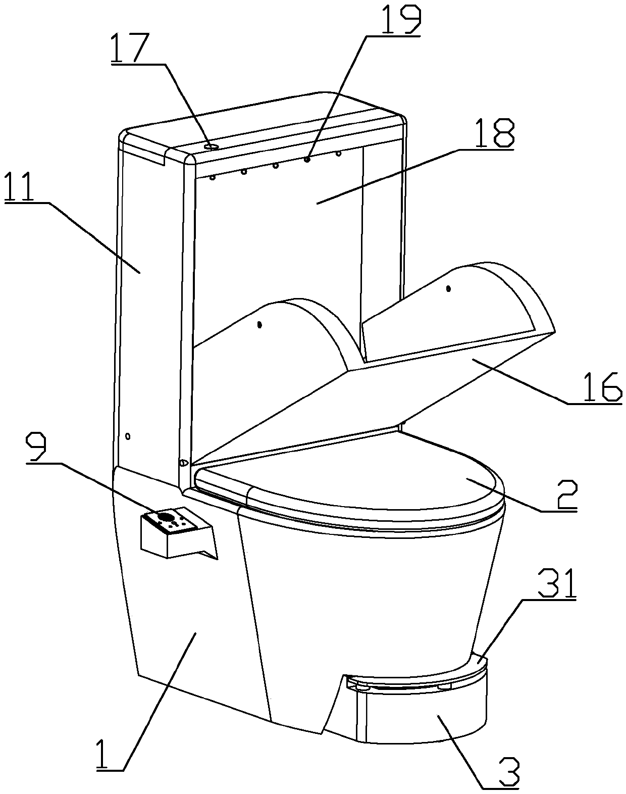
[0082] The front part of the water storage tank is formed with a urinal 18 with a front opening, the lower end of the urinal is a concave receiving groove 182, and the bottom of the receiving trough communicates with the sewer through a pipe; the lower end of the front side of the urinal rotates A cover plate 16 capable of closing the front side of the urinal is connected.
[0083] Two side baffles 161 are symmetrically formed on both sides of the cover plate, and a baffle cavity 181 matching the side baffles is formed on the rear side of the urinal.
[0084] The lower ends of the two side baffles are formed with upwardly extending cavities 162, and a switch for controlling the opening and closing of the cov...
Embodiment 2
[0106] This embodiment makes the following improvements on the basis of Embodiment 1: an air inlet is formed at a position higher than the air suction port in the inner extension or at a position equal to the air suction port, and the air inlet and the air suction port are positioned along the circumferential direction of the toilet trough The phases are staggered; the toilet main body is formed with an air intake passage communicating with the air inlet, and the air intake passage communicates with the outside through the air intake pipe. Or the air intake duct communicates with the indoor space away from the front side of the toilet main body, for example, the inlet of the air intake duct is located in the gap between the rear side of the toilet main body and the wall.
[0107] The continuous suction of the air outlet will form a negative pressure in the range of the toilet. In winter, the air flow from the human buttocks (and thighs) into the toilet will make the user feel c...
Embodiment 3
[0109] combine Figure 1 to Figure 11 As shown, this embodiment makes the following improvements on the basis of embodiment 1: the control panel 9 includes a seat body 91 and a panel 92 fixedly connected to the upper end of the seat body.
[0110] The upper part of the panel is formed with three induction air outlets 922 perpendicular to the panel, Every An air outlet pipe 97 is slidably installed in each of the induction air outlets, and a centrifugal fan 95 is installed in the seat, and the air outlet port 951 of the centrifugal fan is connected to one end of each air outlet pipe positioned at the inside of the panel through a hose.
[0111] An air inlet 921 communicating with the air inlet end of the centrifugal fan is formed on the lower part of the panel.
[0112] A sensor mount 923 is formed above the position corresponding to each induction air outlet on the inner wall of the panel, and there is a gap between each sensor mount and the air outlet pipe at the correspondi...
PUM
 Abstract
Description
Claims
Application Information
 - R&D Engineer
- R&D Manager
- IP Professional
- Industry Leading Data Capabilities
- Powerful AI technology
- Patent DNA Extraction
Browse by: Latest US Patents, China's latest patents, Technical Efficacy Thesaurus, Application Domain, Technology Topic, Popular Technical Reports.
© 2024 PatSnap. All rights reserved.Legal|Privacy policy|Modern Slavery Act Transparency Statement|Sitemap|About US| Contact US: help@patsnap.com