
Part drilling and cleaning device

A technology for cleaning devices and parts, applied in the field of parts processing

Inactive Publication Date: 2019-03-29
象山维治模具有限公司
View PDF1 Cites 4 Cited by
  • Summary
  • Abstract
  • Description
  • Claims
  • Application Information

AI Technical Summary

Problems solved by technology

[0004] The object of the present invention is to provide a part drilling cleaning device to solve the problem of cleaning debris inside blind holes with different aperture sizes, and to collect the cleaned debris at the same time

Method used


Image

  • Part drilling and cleaning device
  • Part drilling and cleaning device
  • Part drilling and cleaning device

Examples


Embodiment Construction

[0020] The following is further described in detail through specific implementation methods:

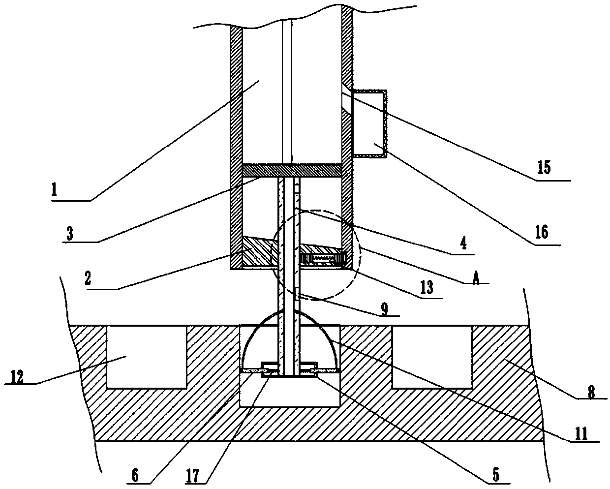
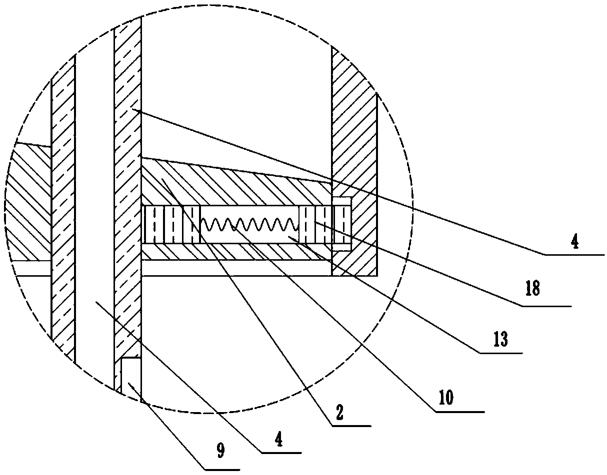
[0021] The reference signs in the drawings of the description include: cleaning box 1, inclined block 2, piston plate 3, connecting rod 4, hollow tube 5, fixed plate 6, rotating plate 7, workbench 8, groove 9, compression spring 10, Air pipe 11 , limiting groove 12 , through hole 13 , cavity 14 , chip outlet 15 , collecting box 16 , first return spring 17 , fixed block 18 , second return spring 19 .

[0022] Examples are attached figure 1 Shown: a parts drilling cleaning device, including a frame, the frame is provided with a cylinder, a cleaning box 1 and a workbench 8 in sequence from top to bottom, the cylinder and the workbench 8 are fixedly connected to the frame, and the cylinder is used as a device The power source of the workbench 8 is provided with a limit groove 12 for different types of parts, and the limit groove 12 is arranged symmetrically with respect to the center li...


PUM


Abstract

The invention belongs to the technical field of part machining, and particularly discloses a part drilling and cleaning device. The part drilling and cleaning device comprises a machine frame, a workbench and a cleaning box are arranged on the machine frame, the cleaning box is located right above the workbench and is in sliding connection with the machine frame, and a plurality of limiting grooves with different sizes are formed in the workbench; an opening is formed in the bottom of the cleaning box, a piston plate is slidably connected in the opening of the bottom of the cleaning box, the piston plate is connected with a cylinder for controlling the piston plate to move up and down, the bottom of the piston plate is fixedly connected with a connecting rod, the interior of the connectingrod is hollow, a hollow tube is arranged at the bottom of the connecting rod, the connecting rod penetrates into the hollow tube and is fixedly connected with the bottom of the hollow tube, a sweeping plate is arranged on the outer side of the hollow tube in the circumferential direction, and the sweeping plate is in sealed sliding connection with the hollow tube. By the adoption of the part drilling and cleaning device, chippings in blind holes of metal parts can be automatically cleared, and centralized processing is carried out on the cleared chippings.

Description

technical field [0001] The invention belongs to the technical field of parts processing, and in particular relates to a part drilling cleaning device. Background technique [0002] Generally speaking, after people use traditional mechanical equipment to perform corresponding drilling on parts, there will often be a lot of debris remaining in the hole. Improve the efficiency and quality of subsequent processing. In the traditional cleaning method, the blind holes of the parts are manually cleaned, but the manual cleaning method is slow, labor-intensive and difficult to clean. [0003] In order to solve the above problems, the patent with the publication number of CN105619164A discloses an automatic inner hole cleaning device for parts drilling, including a workbench, on which a first motor is fixedly installed, and the first motor is connected with a rear sleeve by means of a screw drive. A front sleeve is installed on the front end of the rear sleeve, and a brush is connec...

Claims


Application Information

Patent Timeline
Patent Type & Authority Applications(China)
IPC IPC(8): B23Q11/00
CPCB23Q11/0042B23Q11/0046B23Q11/005
Inventor 毛薇薇
Owner 象山维治模具有限公司
Learn More