Method and device for laser processing chip
A laser processing and chip technology, used in metal processing equipment, laser welding equipment, manufacturing tools, etc., can solve the problems of uneven groove depth and width, damage to the bottom readout circuit, and affect the effective pixel area area. Reduce the influence of groove width and depth uniformity, improve the effect and chip reliability, and improve the effect of pixel utilization
- Summary
- Abstract
- Description
- Claims
- Application Information
AI Technical Summary
Problems solved by technology
Method used
Image
Examples
Embodiment 1
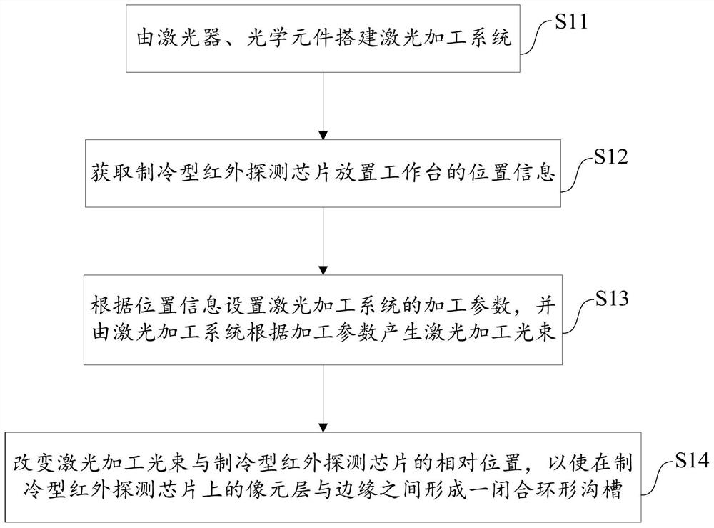
[0066] Embodiments of the present invention provide a method for laser processing chips, such as figure 1 As shown, the method includes:
[0067] S11. Build a laser processing system with lasers and optical components;
[0068] S12. Acquiring the position information of the workbench where the cooled infrared detection chip is placed;
[0069] S13. Set the processing parameters of the laser processing system according to the position information, and generate the laser processing beam according to the processing parameters by the laser processing system;
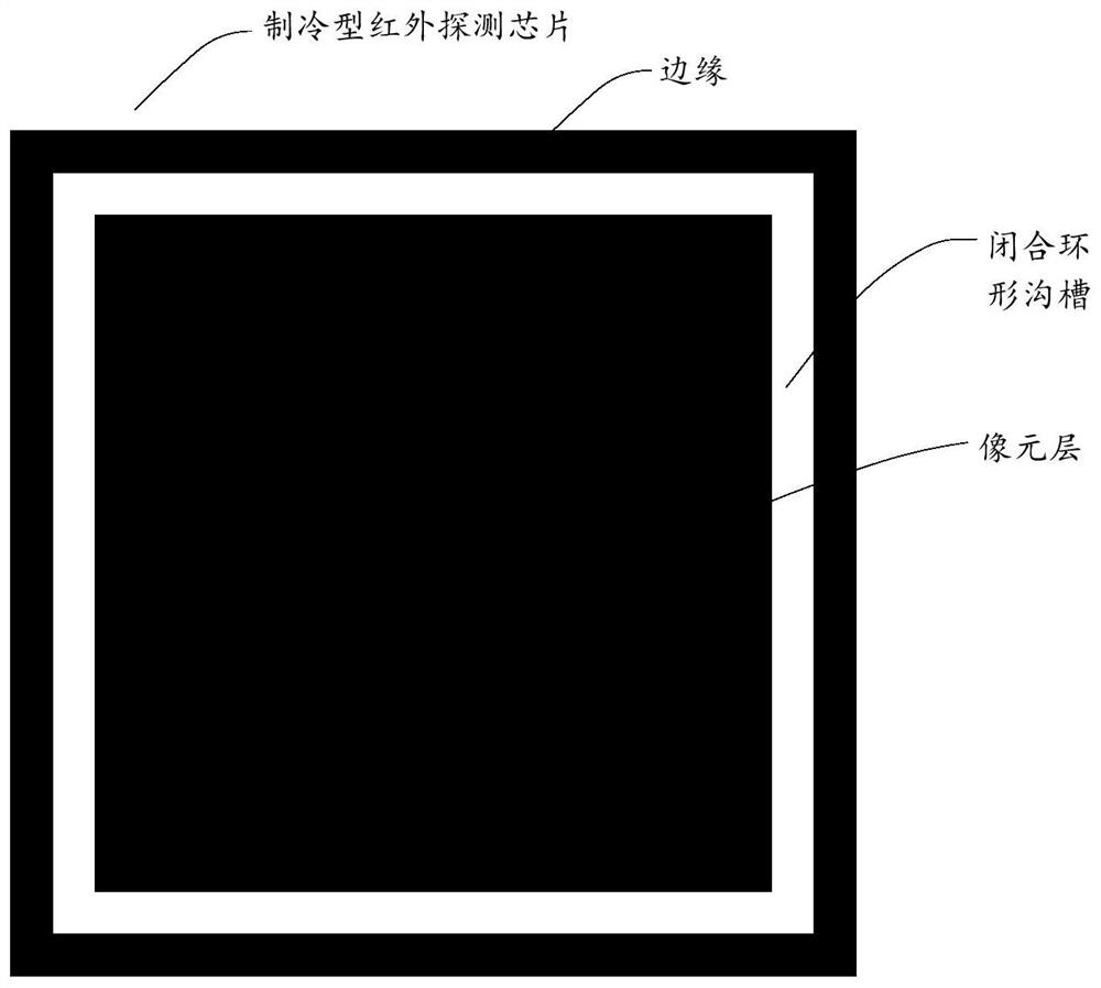
[0070] S14. Changing the relative position of the laser processing beam and the cooled infrared detection chip, so that a closed annular groove is formed between the pixel layer and the edge on the cooled infrared detection chip.
[0071] The method for laser processing chips provided by the embodiments of the present invention mainly uses laser processing systems to generate laser beams to prepare closed annular grooves o...
Embodiment 2
[0124] The difference between this embodiment and Embodiment 1 is that a single laser processing beam can not be used for laser cutting to obtain a groove bottom structure with high flatness. Therefore, the embodiment of the present invention provides a method for laser processing chips, such as Figure 6 As shown, the method includes:
[0125] S41. Build a laser processing system with lasers and optical components;
[0126] S42. Obtain the position information of the workbench where the cooling type infrared detection chip is placed;
[0127] S43. Set the processing parameters of the laser processing system according to the position information, and generate the laser processing beam according to the processing parameters by the laser processing system;
[0128] S44. Process the photosensitive layer of the cooled infrared detector chip with the laser processing beam with the first power to form two parallel grooves, and then process the cooled infrared detector chip between ...
Embodiment 3
[0159] The difference between this embodiment and the above-mentioned embodiment is that the narrower the width of the prepared groove, the better, and the depth just penetrates to the bottom readout chip circuit layer, and the two sides of the groove are steep, which is conducive to the release of stress; therefore, the embodiment of the present invention provides A method of laser processing chips, such as Figure 8 As shown, the method includes:
[0160] S51. Build a workbench with adjustable angle, and place the refrigerated infrared detection chip to be processed on the workbench;
[0161] S52, setting the adjustment and compensation process parameters of the workbench, and the laser parameters of the laser processing system built by the laser and optical components;
[0162] S53. Change the angle of the workbench at least once according to the laser parameters, adjust and compensate the process parameters, so that the laser processing system performs inclined processing...
PUM
| Property | Measurement | Unit |
|---|---|---|
| wavelength | aaaaa | aaaaa |
| height | aaaaa | aaaaa |
Abstract
Description
Claims
Application Information
 - R&D
- Intellectual Property
- Life Sciences
- Materials
- Tech Scout
- Unparalleled Data Quality
- Higher Quality Content
- 60% Fewer Hallucinations
Browse by: Latest US Patents, China's latest patents, Technical Efficacy Thesaurus, Application Domain, Technology Topic, Popular Technical Reports.
© 2025 PatSnap. All rights reserved.Legal|Privacy policy|Modern Slavery Act Transparency Statement|Sitemap|About US| Contact US: help@patsnap.com


