
Ladle pouring device

A technology of ladle device and pouring ladle, which is applied to equipment for feeding molten metal into molds, casting molten material containers, manufacturing tools, etc., which can solve problems such as high energy consumption and cumbersome process, so as to ensure consistency and avoid pouring Out of the mold, precise pouring effect

Active Publication Date: 2019-03-29
广德亚太汽车智能制动系统有限公司
View PDF12 Cites 3 Cited by
  • Summary
  • Abstract
  • Description
  • Claims
  • Application Information

AI Technical Summary

Problems solved by technology

During the pouring process, it is necessary to change the inclination angle of the ladle so that the molten metal in the ladle is poured into the mold. However, when the liquid metal in one ladle is poured into multiple molds, the existing ladle is in the process of pouring. As the molten metal in the ladle decreases, the inclination of the ladle relative to the vertical direction increases, and the horizontal direction of the ladle mouth relative to the mold changes. In the process of pulling the ladle backwards, or changing the position of the mold on the conveying device, the process is cumbersome and the energy consumption is high

Method used


Image

  • Ladle pouring device
  • Ladle pouring device
  • Ladle pouring device

Examples


Embodiment 1

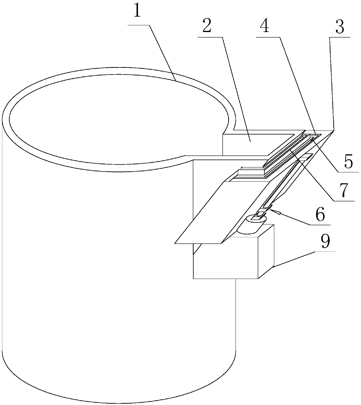
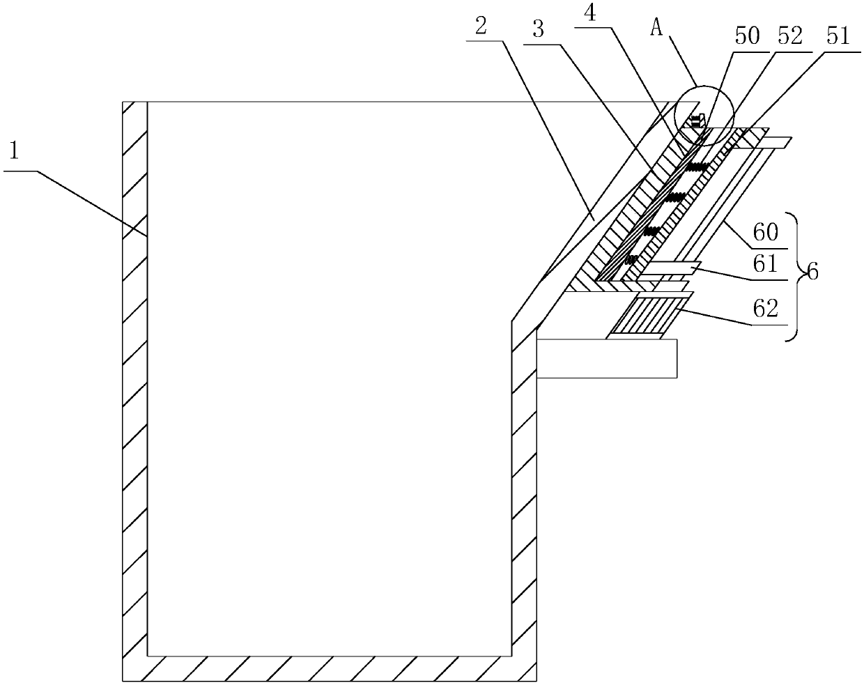
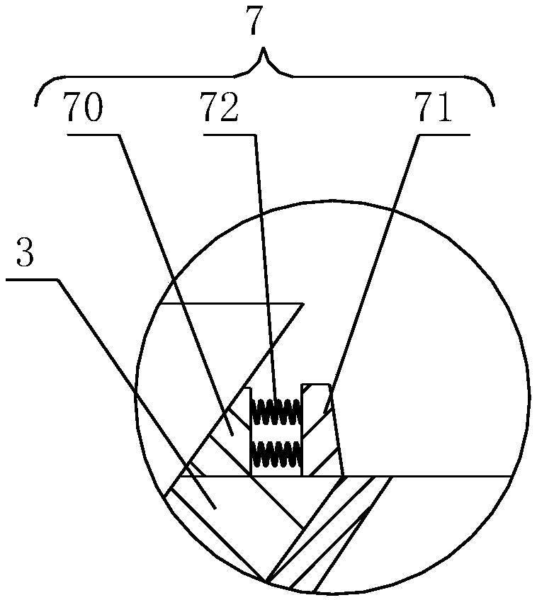
[0024] like Figure 1-6 The ladle device shown includes a ladle body 1, a ladle mouth 2 is provided on the ladle body 1, a guide 3 is provided on the outer wall of the ladle mouth 2, and a deflector 5 is slidably connected to the guide 3, The deflectors 5 are all concave, and the guide 3 has a guide groove 4, the deflector 5 slides in the guide groove 4, the surface of the deflector 5 close to the ladle mouth is parallel to the inner surface of the ladle mouth 2, and the guide The flow plate 5 is connected with the guide member 3 through the sliding mechanism 6 , and the sliding mechanism 6 drives the flow guide plate 5 to move up and down relative to the ladle mouth 2 .

[0025] The sliding mechanism 6 includes a lead screw 60, a slider 61 and a moving element 62, the lead screw 60 is connected to the guide 3 in rotation, the slider 61 is threadedly mounted on the lead screw 60, and the slider 61 is fixedly connected to the deflector 5 , the moving part 62 is connected with ...


PUM


Abstract

The invention discloses a ladle pouring device. The ladle pouring device comprises a ladle pouring body, wherein the ladle pouring body is provided with a ladle pouring opening; a guide part is arranged on an outer wall of the ladle pouring opening; the guide part is in sliding connection with a flow guide plate; the surface, close to the ladle pouring opening, of the flow guide plate is parallelto the inner surface of the ladle pouring opening; the flow guide plate is connected with the guide part through a sliding mechanism; and the sliding mechanism drives the flow guide plate to move up and down relative to the ladle pouring opening. According to the ladle pouring device disclosed by the invention, liquid-state metal of the ladle pouring opening is drained through the flow guide plate; and the sliding mechanism drives the flow guide plate to move relative to the ladle pouring opening and the horizontal position of pouring the liquid-state metal, which flows out from the flow guideplate, into a mold is adjusted.

Description

technical field [0001] The invention relates to the technical field of pouring machinery, in particular to a ladle device. Background technique [0002] The ladle is used for pouring in the foundry workshop. After receiving the molten metal in front of the furnace, it is transported to the casting mold by a truck for pouring. It is divided into ladles, ladles, teapot ladles, and ductile iron ladles. During the pouring process, it is necessary to change the inclination angle of the ladle so that the molten metal in the ladle is poured into the mold. However, when the liquid metal in one ladle is poured into multiple molds, the existing ladle is in the process of pouring. As the molten metal in the ladle decreases, the inclination of the ladle relative to the vertical direction increases, and the horizontal direction of the ladle mouth relative to the mold changes. In the process of pulling the ladle backward, or changing the position of the mold on the conveying device, the ...

Claims


Application Information

Patent Timeline
Patent Type & Authority Applications(China)
IPC IPC(8): B22D41/00B22D35/04
CPCB22D35/04B22D41/00
Inventor 魏明强吴兴远高元
Owner 广德亚太汽车智能制动系统有限公司
Learn More