Self-locking lifting device for refrigerator cold storage interval and working method thereof
A lifting device and refrigerator technology, which is applied to household refrigeration devices, applications, household appliances, etc., can solve problems such as high processing precision requirements, cumbersome maintenance in the later stage, and does not conform to the development trend of the home appliance industry, and achieves a small space occupation and a simple and reasonable structure. The effect of compactness, automation and intelligence
- Summary
- Abstract
- Description
- Claims
- Application Information
AI Technical Summary
Problems solved by technology
Method used
Image
Examples
Embodiment 1
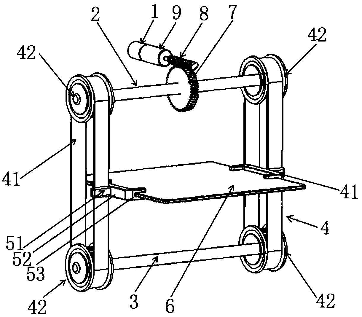
[0027] Such as figure 1The self-locking lifting device for the refrigerated interval of the refrigerator is installed in the cabinet of the refrigerator 12, and includes a motor 1, an upper connecting rod 2, a lower connecting rod 3, a transmission mechanism 4, a connecting mechanism 5 and a partition 6. The connecting rod 2 and the lower connecting rod 3 are respectively connected to two transmission mechanisms 4, the middle part of the upper connecting rod 2 is provided with a helical gear 7, the main shaft of the motor 1 is provided with a worm 8, and the helical gear 7 and the worm 8 mesh, It forms a worm helical gear pair and has a self-locking function. The two transmission mechanisms 4 are respectively provided with connecting mechanisms 5 , and partitions 6 are arranged between the connecting mechanisms 5 and the partitions 6 are fixed.
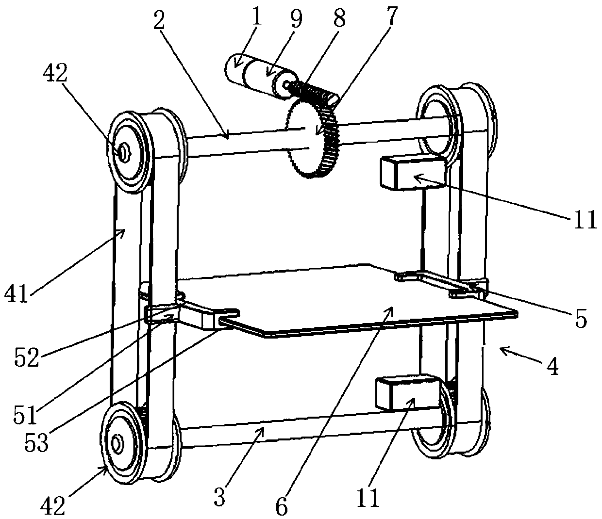
[0028] Among them, such as figure 2 As shown, the motor 1 is a DC motor, and the motor 1 is further provided with a deceleration ...
Embodiment 2
[0033] like figure 1 The self-locking lifting device for the refrigerated interval of the refrigerator is installed in the cabinet of the refrigerator 12, and includes a motor 1, an upper connecting rod 2, a lower connecting rod 3, a transmission mechanism 4, a connecting mechanism 5 and a partition 6. The connecting rod 2 and the lower connecting rod 3 are respectively connected to two transmission mechanisms 4, the middle part of the upper connecting rod 2 is provided with a helical gear 7, the main shaft of the motor 1 is provided with a worm 8, and the helical gear 7 and the worm 8 mesh, It forms a worm helical gear pair and has a self-locking function. The two transmission mechanisms 4 are respectively provided with connecting mechanisms 5 , and partitions 6 are arranged between the connecting mechanisms 5 and the partitions 6 are fixed.
[0034] Among them, such as image 3 As shown, the motor 1 is a DC motor, and the motor 1 is further provided with a deceleration mod...
PUM
 Abstract
Description
Claims
Application Information
 - R&D
- Intellectual Property
- Life Sciences
- Materials
- Tech Scout
- Unparalleled Data Quality
- Higher Quality Content
- 60% Fewer Hallucinations
Browse by: Latest US Patents, China's latest patents, Technical Efficacy Thesaurus, Application Domain, Technology Topic, Popular Technical Reports.
© 2025 PatSnap. All rights reserved.Legal|Privacy policy|Modern Slavery Act Transparency Statement|Sitemap|About US| Contact US: help@patsnap.com


