Wind driven generator yawing device capable of effectively withstanding strong wind attack

A wind turbine and yaw technology, applied in wind turbine components, wind turbines, wind power generation, etc., can solve the problems of economic loss, the blade cannot be too large, and the speed is out of control.

Inactive Publication Date: 2014-04-16
WINDPOWER ENERGY CO LTD SHUNDE
View PDF6 Cites 2 Cited by
  • Summary
  • Abstract
  • Description
  • Claims
  • Application Information

AI Technical Summary

Problems solved by technology

However, the blade should not be too large. If it is too large, the wind blade will be severely bent towards the generator trunk in case of strong wind, or even break the generator trunk, causing huge economic losses, so the efficiency of the generator is limited to a certain extent; In addition, in the state of strong wind, it is easy to cause the speed to be out of control. After exceeding the maximum speed set by the generator, it still does not stop. Accompanying it is the overcurrent of the generator, which seriously damages the internal structure of the generator and causes the phenomenon of speeding

Method used


Image

  • Wind driven generator yawing device capable of effectively withstanding strong wind attack
  • Wind driven generator yawing device capable of effectively withstanding strong wind attack
  • Wind driven generator yawing device capable of effectively withstanding strong wind attack

Examples


Embodiment Construction

[0023] The present invention will be described in further detail below in conjunction with the accompanying drawings and embodiments.

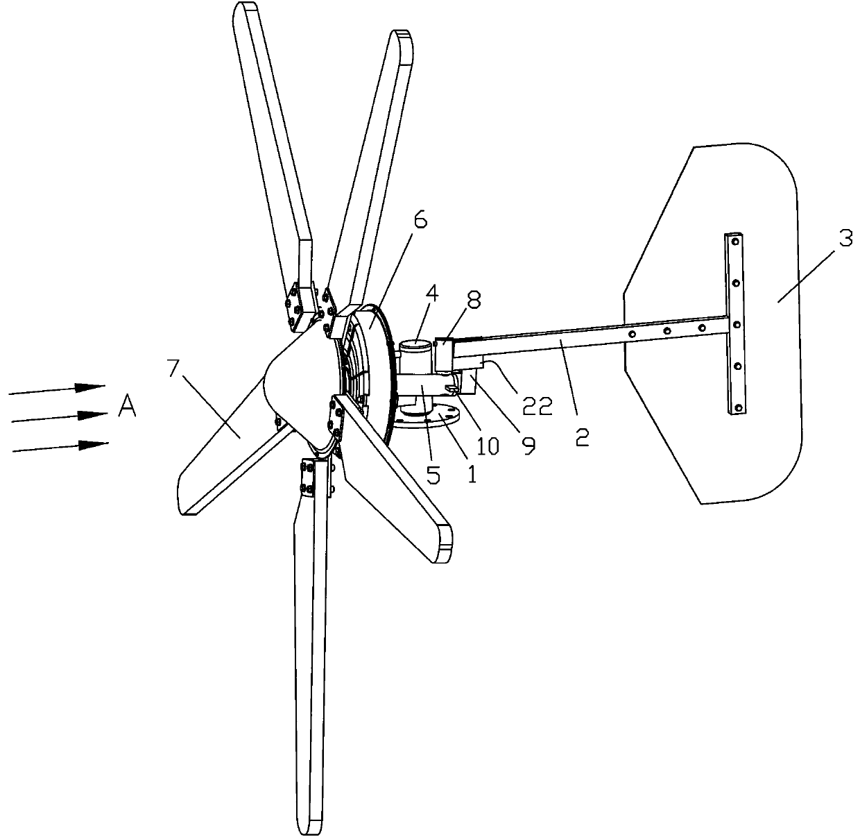
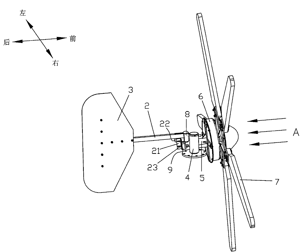
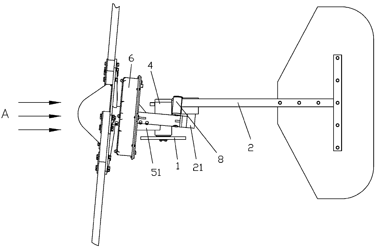
[0024] refer to Figure 1~Figure 10 , a kind of yaw device for wind power generators that effectively resists strong wind attacks of the present invention includes a yaw fixing seat 1 and a tail rudder stock 2, and a tail rudder plate 3 is installed at the tail of the tail rudder stock 2, and the yaw fixing seat 1 is installed with a yaw rotating seat 4, which can rotate in the horizontal plane. In this embodiment, the yaw rotating seat 4 is a cylindrical part, and the yaw rotating seat 4 is sleeved on the yaw fixed seat 1 on the vertical shaft (not shown), wherein the two ends of the yaw rotating base 4 are connected to the vertical shaft bearings, the yaw rotating base 4 is provided with a connecting arm 5, and a generator is installed at the front end of the connecting arm 5 6. Blades 7 are set at the front of the generator 6, and the rota...


PUM


Abstract

The invention discloses a wind driven generator yawing device capable of effectively withstanding strong wind attack. A connection arm is eccentrically mounted relative to a yawing rotary seat, a tail vane rotary sleeve is rotatably connected onto the connection arm and positioned behind the yawing rotary seat, and the tail vane rotary sleeve is in a tilted arrangement in a way that the higher the tail vane rotary sleeve is, the closer the tail vane rotary sleeve approaches to the side of the yawing rotary seat. A tail vane rod is fixed onto the tail vane rotary sleeve, a first limiting block and a second limiting block are positioned on two sides of the tail vane rod respectively and arranged on the connection rod, and a limiting plate is arranged on the tail vane rod. A tail vane plate is perpendicular to a vane rotation surface when the first limiting block and the limiting plate are in abutted connection. The tail vane plate is parallel to the vane rotation surface when the connection arm rotates relative to the tail vane rod to drive the second limiting block to be in abutted connection with the limiting plate. The wind driven generator yawing device has the advantages of simplicity, reasonability and compactness in structure, convenience in installation, low implementation cost, capability of automatically adjusting vane rotation speed according to wind speed, avoidance of galloping and the like.

Description

technical field [0001] The present invention relates to power generating equipment, in particular wind generators. Background technique [0002] Utilizing natural renewable resources such as solar energy and wind energy to replace limited energy sources such as fuel oil has become an important strategy to solve energy problems. As one of the important ways to utilize renewable resources in nature, wind turbines use wind energy to convert it into electrical energy, and then apply the produced electrical energy to various fields of daily life. Most current wind turbines use propeller blades to receive wind power. However, the blade should not be too large. If it is too large, the wind blade will be seriously bent towards the generator trunk in case of strong wind, or even break the generator trunk, causing huge economic losses, so the efficiency of the generator is limited to a certain extent; In addition, in the state of strong wind, it is easy to cause the speed to be out ...

Claims


Application Information

Patent Timeline
Patent Type & Authority Applications(China)
IPC IPC(8): F03D11/00
CPCY02E10/722Y02E10/72Y02P70/50
Inventor 李台
Owner WINDPOWER ENERGY CO LTD SHUNDE
Why Eureka
Try Eureka