
Polarization maintaining optical fiber end surface axis alignment device and method

A polarization-maintaining fiber, fiber end face technology, applied in polarization fiber, cladding fiber, optics, etc., can solve the problems of inconspicuous imaging features, difficulty, limited work efficiency and application scope, etc., to achieve easy implementation, cost reduction, Guaranteed effect of concentricity

Active Publication Date: 2019-03-22
BEIJING AEROSPACE TIMES OPTICAL ELECTRONICS TECH
View PDF12 Cites 9 Cited by
  • Summary
  • Abstract
  • Description
  • Claims
  • Application Information

AI Technical Summary

Problems solved by technology

For this type of polarization-maintaining fiber, the imaging characteristics are not obvious, and it is difficult to detect the polarization axis directly through side-illuminated imaging observation, and the alignment process sometimes requires the use of matching fluid, which also limits the work efficiency and application range

Method used


Image

  • Polarization maintaining optical fiber end surface axis alignment device and method
  • Polarization maintaining optical fiber end surface axis alignment device and method
  • Polarization maintaining optical fiber end surface axis alignment device and method

Examples


Embodiment Construction

[0045] The present invention will be described in detail below in conjunction with the accompanying drawings and specific embodiments.

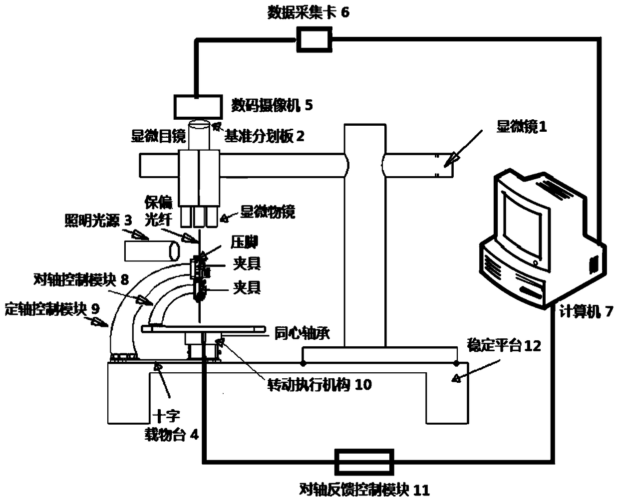
[0046] Such as figure 1 As shown, the present invention provides an end-to-axis device for polarization-maintaining optical fibers. The end-to-axis device includes a microscope 1, an illumination light source 3, a cross stage 4, an axis control module 8, and an axis control module 9 and an actuator 10 for precise rotation of the polarization-maintaining optical fiber; where a reference line is provided in the field of view of the microscope eyepiece, the polarization-maintaining optical fiber a is cut at the end face, and the cutting angle is not greater than 1.5°, and the polarization-maintaining optical fiber after the end face cutting is processed by Clamp the clamp of the axis control module 8, place the end face of the polarization-maintaining fiber to be aligned under the microscope objective; the illumination source 3 is used to illumi...


PUM


Abstract

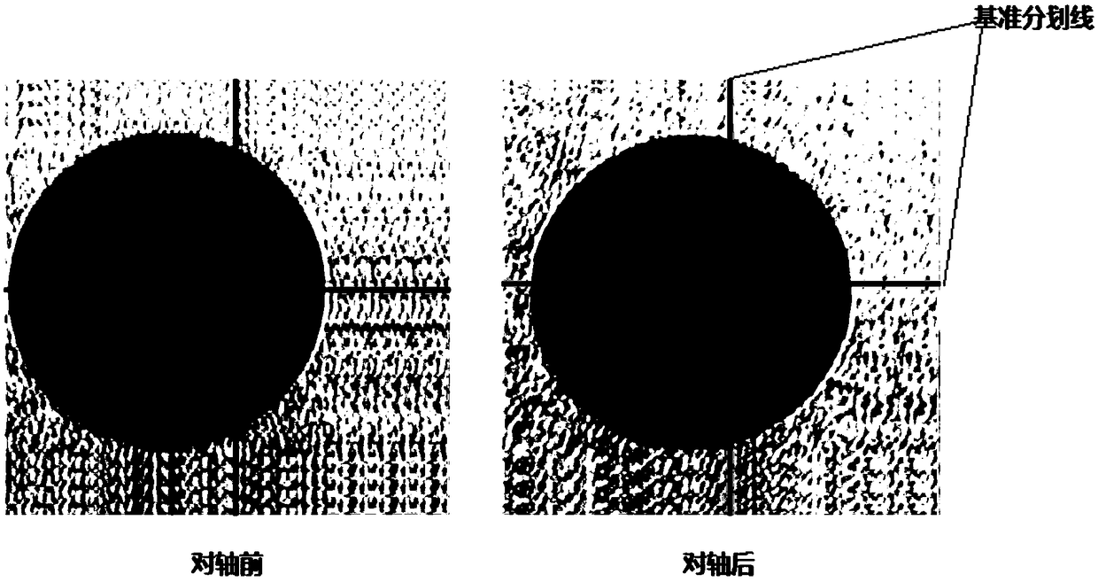
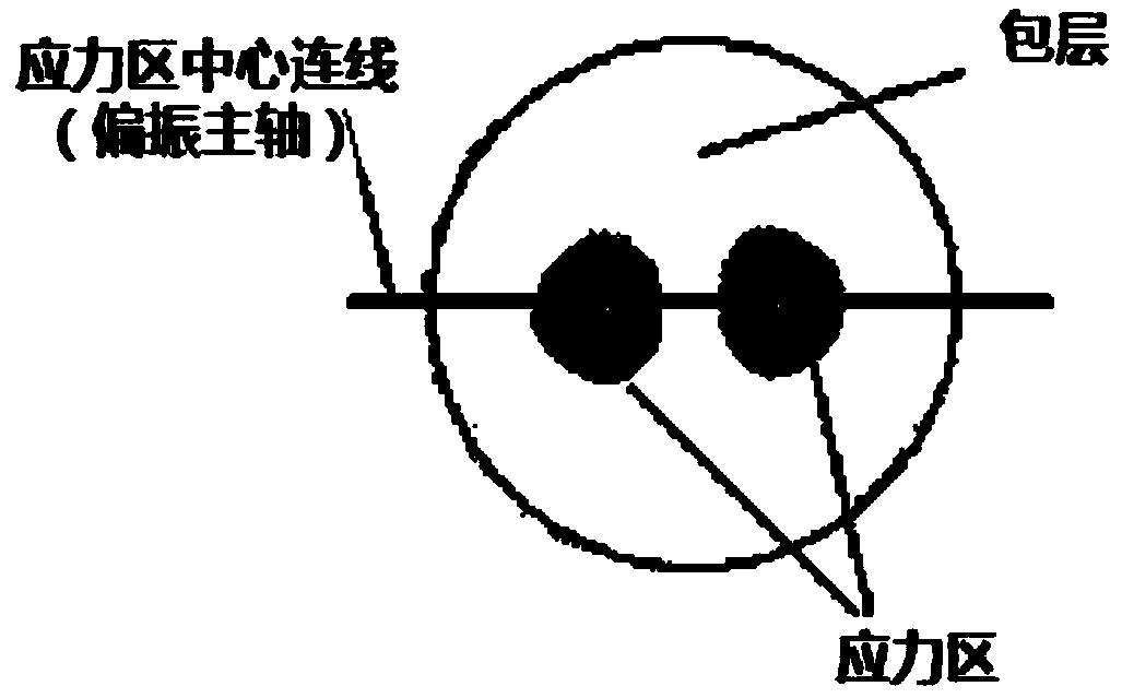
The invention provides a polarization maintaining optical fiber end surface axis alignment device and method. The polarization maintaining optical fiber end surface axis alignment device comprises a microscope, a light source, a crossed objective table, an axis alignment control module, an axis direction control module and an executing mechanism, wherein the ocular view of the microscope is provided with a reference line; polarization-maintaining optical fiber with the end surface cut is clamped by a fixture of the axis alignment control module, and the end surface of a polarization-maintaining optical fiber to be axis-aligned is arranged under the objective of the microscope; the light source is used for lighting up the side cladding layer of the polarization-maintaining optical fiber sothat the stress area of the end surface of the polarization-maintaining optical fiber to be axis-aligned can be positioned inside the view of the objective of the microscope; the axis alignment control module and the crossed objective table are fixedly connected; the executing mechanism is used for adjusting the crossed objective table to drive the axis alignment control module to rotate so that the contour of the stress area of the end surface of the polarization-maintaining optical fiber is tangential to the reference line inside the ocular view of the microscope to achieve shaft alignment between the end surface of e polarization-maintaining optical fiber and the reference line; the axis direction control module is used for clamping the axis-aligned polarization-maintaining optical fiber through the clamping plates of the fixture to achieve axis direction between the end surface of the polarization-maintaining optical fiber and the reference line.

Description

technical field [0001] The invention relates to a polarization-maintaining optical fiber end-to-axis device and method, and belongs to the technical field of electronic optical fibers. Background technique [0002] Polarization-maintaining optical fiber is an important basic equipment for coherent optical communication and coherent optical fiber sensing system. By artificially creating birefringence in the fiber, the propagation constants of the two linear polarization fundamental modes in the polarization-maintaining fiber have a large difference to effectively suppress the random unstable inter-mode coupling during propagation, thereby achieving polarization-maintaining performance and high The transmission requirements of precision signals. In theory, the sensitivity of coherent detection method can be increased by nearly 20dB compared with direct amplitude detection; therefore, the coherent optical fiber sensor with polarization-maintaining optical fiber as the main body...

Claims


Application Information

Patent Timeline
IPC IPC(8): G02B6/024G02B21/36G02B21/34
CPCG02B6/024G02B21/34G02B21/361
Inventor 马玉洲杨清生单联洁葛文谦龙娅刘朝阳杨广洁赵立凯
Owner BEIJING AEROSPACE TIMES OPTICAL ELECTRONICS TECH
Learn More