
Contrast method for single sand body inside composite sand body of offshore oilfield

A technology for offshore oilfields and single sand bodies, which is applied to seismology, measuring devices, instruments, etc. for logging records. Solving problems such as sedimentary origin and internal structure relationship, achieving the effect of accurate description, objective sand body division and comparison results, and reduced ambiguity

Active Publication Date: 2019-03-22
CNOOC TIANJIN BRANCH +1
View PDF2 Cites 9 Cited by
  • Summary
  • Abstract
  • Description
  • Claims
  • Application Information

AI Technical Summary

Problems solved by technology

There are three problems in the traditional sand body correlation: ①The sand bodies in the same sublayer or unit are all connected, which does not reflect the sedimentary origin and internal structural relationship
③ The timeliness of sand bodies between wells needs to be verified
The traditional comparison method can only show the spatial distribution of sand bodies, and it is difficult to reflect the sand body level, so as to realize reservoir prediction and evaluation
Its fundamental limitation is that this method cannot solve the heterogeneity problem inside the reservoir, and analyze the internal structure, connectivity and injection-production effect relationship of the reservoir sand body. Therefore, in the later stage of offshore oilfield development, this method The drawn maps are not convenient for application and practice

Method used


Image

  • Contrast method for single sand body inside composite sand body of offshore oilfield
  • Contrast method for single sand body inside composite sand body of offshore oilfield
  • Contrast method for single sand body inside composite sand body of offshore oilfield

Examples


Embodiment

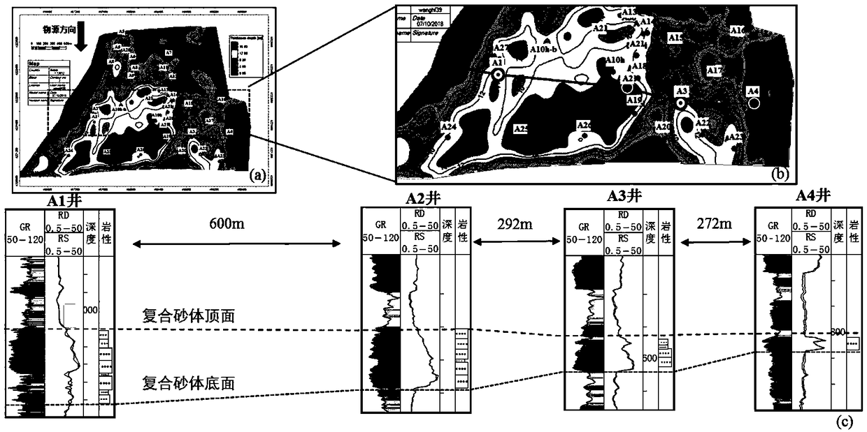
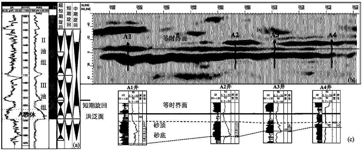
[0030] A method for comparing a single sand body inside a composite sand body in an offshore oilfield according to the present invention will be further described by taking the A sand body of the BZ oilfield in the eastern part of China as an example.

[0031] The lower member of the Minghuazhen Formation in the BZ oilfield is a distributary sand bar type shallow water delta facies sedimentary strata. The level of the oil formation is equivalent to the mid-cycle scale. There are 23 wells in the A sand body.

[0032] Aiming at the target composite sand body of A sand body in the lower section of Minghuazhen Formation III oil group in this area, the present invention adopts the following technical scheme to compare the composite sand bodies:

[0033] 1. Selection of backbone section. The backbone profile satisfies (1) the profile is perpendicular to the provenance direction, that is, transverse to the long axis of the sedimentary body; (2) the single wells in the profile are mai...


PUM


Abstract

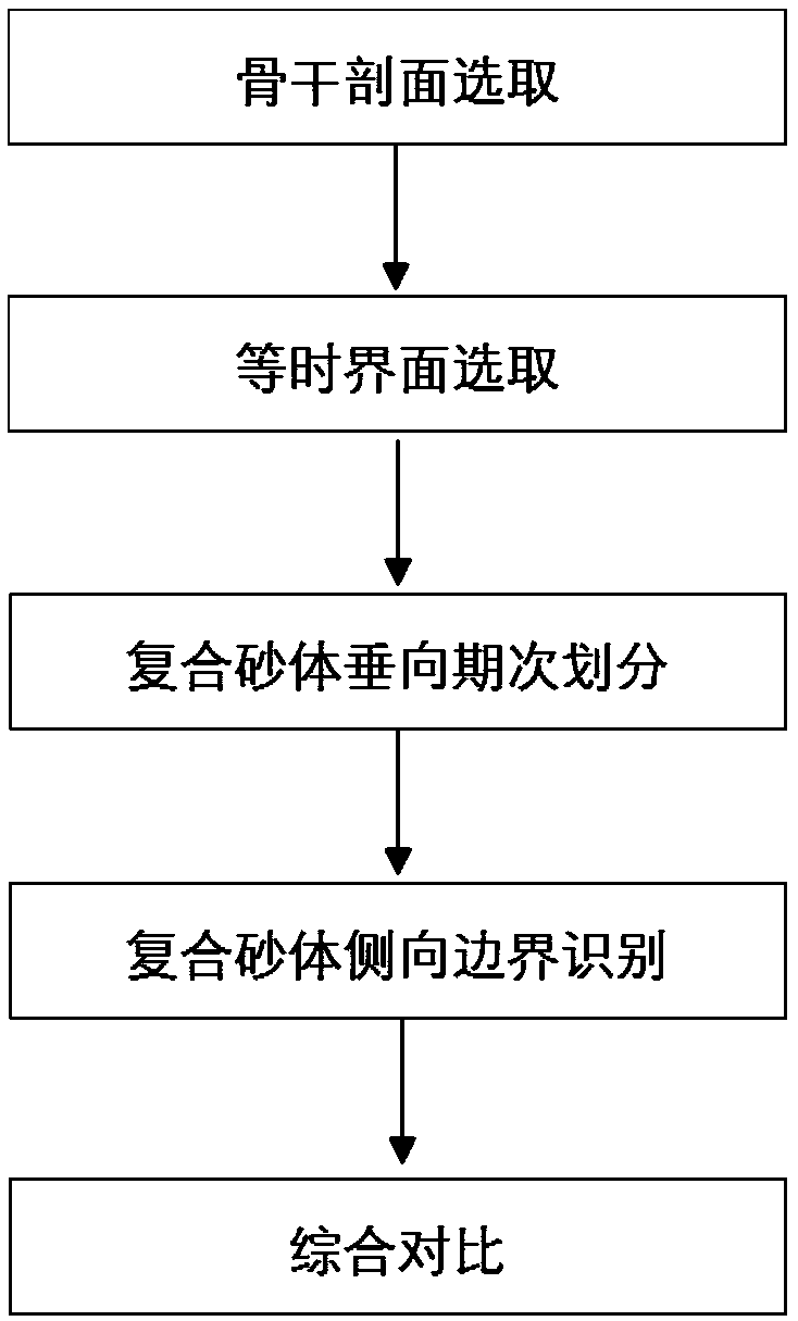
The invention discloses a contrast method for a single sand body inside a composite sand body of an offshore oilfield. The contrast method comprises the following steps of measuring a section of a transection sedimentary body of the cross-well composite sand body of the offshore oilfield in a long-axis direction to obtain a backbone section of the composite sand body; aiming at the selected backbone section, selecting gyration flooding surface mud rock top face in the middle period or short period of the composite sand body to obtain an isochronal interface with the leveled flooding surface mud rock top face; leveling the isochronal interface, and dividing the vertical development phases of the composite sand body on the interface according to earthquake, logging and well data of a measured single well; on the basis of the divided development phases, recognizing lateral boundaries of the cross-well composite sand body according to the sensitive earthquake attributes; analyzing the interior structure of the composite sand body according to the vertical development phases and the lateral boundaries of the composite sand body to obtain contrast of the single sand body inside the composite sand body. According to the contrast method, the structural relation inside the sand body can be given; the relation of the cross-well sand body is accurately described through the further utilization of the offshore oilfield earthquake data.

Description

technical field [0001] The invention relates to a method for comparing a single sand body inside a composite sand body in an offshore oil field, and belongs to the field of oil and gas field development. Background technique [0002] At present, in the process of exploration and development of oil fields, it often occurs that the oil production wells close to the water injection wells are not effective, while the oil production wells farther away from the water injection wells have better connectivity. It is found through research that most of the laterally stable distributed sand bodies are actually stable distributed composite sand bodies. Composite sand bodies are formed during the sedimentary evolution of rivers and deltas. Due to changes in the base level, terrain gradient, and hydrodynamic conditions, the channels and sand bars continue to migrate and swing vertically and laterally. form. Composite sand bodies are formed by splicing and superimposing multiple single ...

Claims


Application Information

Patent Timeline
IPC IPC(8): G01V1/50
CPCG01V1/50G01V2210/6169G01V2210/624
Inventor 范廷恩何明薇王海峰张晶玉高玉飞张显文肖大坤汤婧梁旭于斌
Owner CNOOC TIANJIN BRANCH
Learn More