
Fully automatic pipe fitting bending machine

A pipe bending and fully automatic technology, applied in the field of automation, can solve problems such as unsuitability for mass production and large errors, and achieve the effects of saving manpower, high speed and high efficiency

Pending Publication Date: 2019-03-22
三之信(天津)自动化设备有限公司
View PDF1 Cites 0 Cited by
  • Summary
  • Abstract
  • Description
  • Claims
  • Application Information

AI Technical Summary

Problems solved by technology

[0003] The above-mentioned pipe bending device requires manual loading and unloading, and manual control of the bending position and bending angle. The error is relatively large, and it is not suitable for mass production.

Method used


Image

  • Fully automatic pipe fitting bending machine
  • Fully automatic pipe fitting bending machine
  • Fully automatic pipe fitting bending machine

Examples


Embodiment Construction

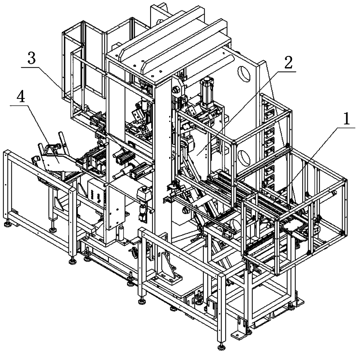
[0025] The present invention will be further described in detail below in conjunction with the accompanying drawings and through specific embodiments. The following embodiments are only descriptive, not restrictive, and cannot limit the protection scope of the present invention.

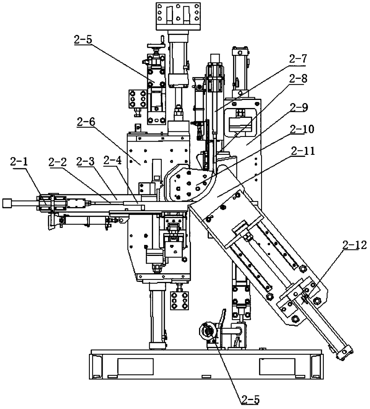
[0026] A fully automatic pipe fitting bending machine, comprising a pipe fitting input and transfer unit 1 , a pipe fitting clamping unit 3 , a bending unit 2 , and a finished product taking out unit 4 .

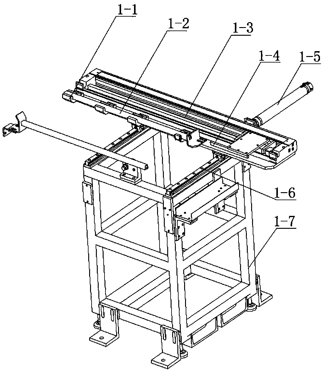
[0027] The pipe fitting input transfer unit includes a reclaiming cylinder 1-5, a pusher rodless cylinder 1-3, and two guide rails 1-6 are fixed on the top surface of the frame 1-7 in parallel and spaced apart, and are slidably installed between the two guide rails. A support plate, the rear end of the support plate is connected with a reclaiming cylinder, the reclaiming cylinder pushes the support plate to slide back and forth, a push rodless cylinder is fixed on the support plate, and a push rodle...


PUM


Abstract

The invention relates to a fully automatic pipe fitting bending machine. The bending machine comprises a pipe fitting input transmission unit, a pipe fitting clamping unit, a bending unit and a finished product taking out unit. After a pipe fitting is placed into an input work station, the pipe fitting is automatically transferred to the bending unit for fixing and bending, and after completion, the pipe fitting is automatically discharged. The fully automatic pipe fitting bending machine has the beneficial effects that the speed is high, the efficiency is high, and the manpower is saved.

Description

technical field [0001] The invention belongs to the field of automation, and relates to pipe bending technology, in particular to a fully automatic pipe bending machine. Background technique [0002] Some parts are made by folding pipe into shape. CN108746276A discloses a pipe bending device suitable for thin-walled square pipes of different sizes. There are pipe bending rollers matched with the pipe bending rollers. The outer circumferences of the pipe bending rollers and the pipe bending rollers are respectively provided with rectangular grooves for cooperating with the thin-walled square pipes. The horizontal compression adjustment device for the distance between the pipe bending wheels can install thin-walled square pipes with different widths in the two rectangular grooves by adjusting the horizontal compression adjustment device. The bending arm is located between the two rectangular grooves and a vertical compression adjustment device is installed. Thin-walled squar...

Claims


Application Information

Patent Timeline
Patent Type & Authority Applications(China)
IPC IPC(8): B21D7/025B21D43/20B21D43/02
CPCB21D7/025B21D43/02B21D43/20
Inventor 王金凤
Owner 三之信(天津)自动化设备有限公司
Learn More