Vacuum reacting and testing device

A testing device and reaction technology, applied in the field of chemistry, can solve the problems of complicated connection method of sample holder, introduction of impurities, complicated operation process, etc., and achieve the effects of simple transfer and fixing method, avoidance of operation process, and simple operation process

Pending Publication Date: 2019-03-22
JINHUA VOCATIONAL TECH COLLEGE
View PDF0 Cites 0 Cited by
  • Summary
  • Abstract
  • Description
  • Claims
  • Application Information

AI Technical Summary

Problems solved by technology

[0002] Many chemical reactions, such as some gas-phase catalytic reactions, need to be carried out in a vacuum environment, that is, the chemical reactions of the reactants and subsequent characteristic tests are located in a vacuum chamber, and some special reaction processes need to be carried out in an ultra-high vacuum environment. The reagent is directly dropped on the surface of the solid sample. The first defect of the prior art: in the prior art, it is usually necessary to transfer the solid sample to the outside of the vacuum environment or pass a protective gas into the vacuum chamber. The operation process is cumbersome and impurities will be introduced. In addition, In some experiments, there is no permanent electrical connection between the sample and the sample transfer rod and the vacuum cavity, and a simple fixing structure is required to implement the electrical test; defect 2 of the prior art: the connection mode of the sample seat in the prior art is relatively complicated , the vacuum reaction and testing device can solve the problem

Method used


Image

  • Vacuum reacting and testing device
  • Vacuum reacting and testing device
  • Vacuum reacting and testing device

Examples


Embodiment Construction

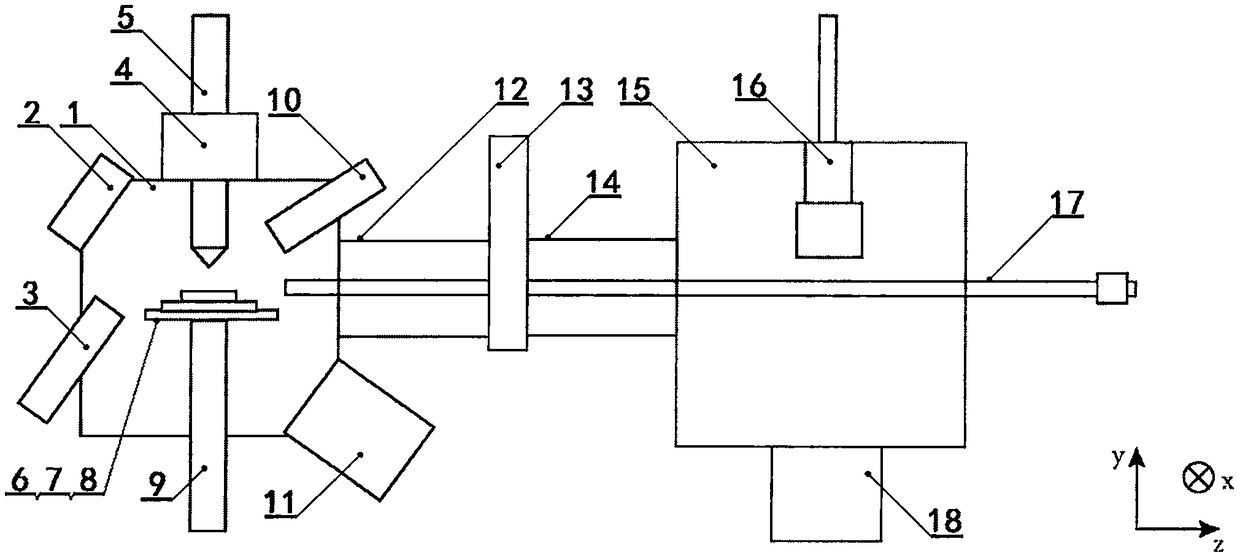
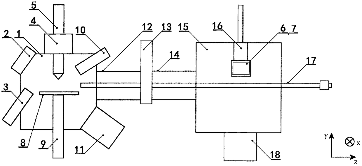
[0033] Such as figure 1 It is a schematic diagram when the sample seat of the present invention is located in the reaction chamber, such as figure 2It is a schematic diagram when the sample seat of the present invention is located in the test chamber, including a reaction chamber (1), an observation window (2), a liquid container (3), a linear drive (4), a cooling rod (5), a sample (6), a sample seat ( 7), sample table (8), metal rod (9), gas inlet (10), vacuum pump I (11), bellows I (12), gate valve (13), bellows II (14), test chamber (15 ), sample holder (16), transmission rod (17), vacuum pump II (18) and test circuit, xyz is a three-dimensional space coordinate system, and the outside of test chamber (15) is connected with vacuum pump II (18) and test circuit, vacuum pump I ( 11) An absorption pump cooled by liquid nitrogen, the reaction chamber (1), bellows I (12), gate valve (13), bellows II (14) and test chamber (15) are connected in sequence, when the gate valve (13)...


PUM

PropertyMeasurementUnit
Lengthaaaaaaaaaa
The inside diameter ofaaaaaaaaaa
Lengthaaaaaaaaaa

Abstract

The invention relates to the field of chemistry, in particular to a vacuum reacting and testing device. The vacuum reacting and testing device comprises a reaction chamber, an observation window, a liquid container, a linear driver, a cooling rod, a sample, a sample carrier, a sample platform, a metal rod, a gas inlet, a vacuum pump I, a corrugated pipe I, a door valve, a corrugated pipe II, a testing chamber, a sample holder, a transfer rod, a vacuum pump II and a test circuit. The vacuum reacting and testing device is used for chemical reactions of film samples in vacuum, liquid reagents aredirectly dripped onto the surface of the solid sample by melting the pre-frozen reagents in a vacuum environment, and in a reaction needing the liquid reagents, the solid sample is not needed to be transferred out of the vacuum environment or a protection gas is not needed into a vacuum chamber, so that sudden reduction of the vacuum degree around the sample is prevented, the operation process issimple, and introduction of impurities is avoided; the vacuum reacting and testing device has a simple sample carrier transfer and fixation method, and can be used for electrical measurement immediately after chemical reaction of the sample.

Description

technical field [0001] The invention relates to the field of chemistry, in particular to a vacuum reaction and testing device used for chemical reaction of film samples in vacuum. Background technique [0002] Many chemical reactions, such as some gas-phase catalytic reactions, need to be carried out in a vacuum environment, that is, the chemical reactions of the reactants and subsequent characteristic tests are located in a vacuum chamber, and some special reaction processes need to be carried out in an ultra-high vacuum environment. The reagent is directly dropped on the surface of the solid sample. The first defect of the prior art: in the prior art, it is usually necessary to transfer the solid sample to the outside of the vacuum environment or pass a protective gas into the vacuum chamber. The operation process is cumbersome and impurities will be introduced. In addition, In some experiments, there is no permanent electrical connection between the sample and the sample ...

Claims


Application Information

Patent Timeline
IPC IPC(8): B01J3/03B01J19/00G01N27/00G01R31/00B01J4/00
CPCB01J3/03B01J4/001B01J19/00G01N27/00G01R31/00
Inventor 张向平方晓华赵永建
Owner JINHUA VOCATIONAL TECH COLLEGE
Why Eureka
Try Eureka