Digital Accurate Delay Matching Circuit

A matching circuit and digital technology, applied in the field of digital precise time delay matching circuit, can solve the problems of high pass frequency band, cannot be realized at the same time, limited adjustable accuracy, etc., achieves good versatility, high delay adjustment accuracy, Effects with a wide range of delay adjustments

Active Publication Date: 2022-04-12
NAVAL UNIV OF ENG PLA
View PDF8 Cites 0 Cited by
  • Summary
  • Abstract
  • Description
  • Claims
  • Application Information

AI Technical Summary

Problems solved by technology

Fixed delay devices, which can be implemented using PCB transmission lines or dedicated passive delay line devices, have the advantage of high passable frequency bands, but due to the fixed delay value, poor adjustability and poor versatility
Adjustable delay, adjustable delay, flexible use, but the frequency band is narrow, the adjustable range is limited, the adjustable accuracy is limited, and the delay adjustment is very inconvenient by manually adjusting the knob
Whether it is a fixed delayer or an adjustable delayer, it is impossible to simultaneously meet the delay matching requirements of a high applicable signal frequency band ≥ 500MHz, a wide adjustable delay range, microsecond adjustable levels, and a high adjustable delay accuracy within 55.6ps.
At present, no patent or literature has been found to discuss the design of delayers that meet the delay matching requirements

Method used


Image

  • Digital Accurate Delay Matching Circuit
  • Digital Accurate Delay Matching Circuit
  • Digital Accurate Delay Matching Circuit

Examples


Embodiment Construction

[0018] The present invention will be further described in detail below with reference to the accompanying drawings and specific embodiments, so as to facilitate a clear understanding of the present invention, but they do not limit the present invention.

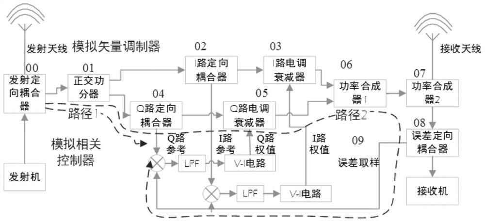
[0019] figure 1 A block diagram of a general adaptive interference cancellation device is shown, which consists of an analog vector modulator and an analog correlation controller. The analog vector modulator completes the extraction, decomposition, adjustment, synthesis and error signal extraction of the reference signal, and the analog correlation controller completes the correlation multiplication and low-pass filter of the signal. Delay matching means that the phase of the reference signal when it reaches both ends of the analog multiplier after passing through path 1 and path 2 is still the same. Path 1 includes quadrature power divider 01, Q-way directional coupler 04 coupling output, path 2 includes quadrature power di...


PUM


Abstract

The invention discloses a digital precise time delay matching circuit, which is used for the time delay matching adjustment of an adaptive interference cancellation device in the 2MHz-500MHz short-wave and ultra-short wave band, including an ADC sampling unit, a clock generator unit, a data synchronization unit and FPGA delay unit. Delay matching adjustment is based on delayed clock sampling technology, by applying sampling clocks of different phases to the sampling ADC, and then implementing data synchronization to achieve delay matching of different paths. Combining the fine sampling clock delay characteristics of the clock generator unit and the large-scale coarse delay adjustment characteristics of the FPGA delay unit, this circuit can realize large-scale, high-precision delay matching adjustment, and the adjustment accuracy is within 55ps.

Description

technical field [0001] The invention relates to the technical field of radio frequency equipment, in particular to a digital precise time delay matching circuit. Background technique [0002] Modern communication platforms integrate numerous radio frequency equipment such as communication, navigation, radar, electronic warfare, etc. High-power transmitters and high-sensitivity receivers need to work on the same platform. The transceiver antennas of the device are densely distributed on the platform, and the complex coupling relationship between the antennas leads to the increasingly prominent electromagnetic compatibility problem of each device inside the platform. When the high-power transmitter is working, due to the limited isolation of the transceiver antenna, a large interference signal will be generated on the adjacent receiver, and in severe cases, the receiver will be blocked or even damaged. [0003] The adaptive interference cancellation technology based on orthog...

Claims


Application Information

Patent Timeline
Patent Type & Authority Patents(China)
IPC IPC(8): H03K5/133H03K5/135H04B1/10
CPCH03K5/133H03K5/135H04B1/10
Inventor 邢金岭葛松虎孟进何方敏李毅王青
Owner NAVAL UNIV OF ENG PLA
Why Eureka
Try Eureka