Swivel tube with compact liquid cooling

A liquid-cooled structure and compact technology, which is applied to the shell/container of the transit-time electronic tube, the electronic tube with velocity/density modulation electron flow, the discharge tube, etc. Limit and other issues, to avoid circumferential flow, improve heat dissipation performance, increase the effect of circulation rate

Active Publication Date: 2021-08-06
INST OF APPLIED ELECTRONICS CHINA ACAD OF ENG PHYSICS
View PDF5 Cites 0 Cited by
  • Summary
  • Abstract
  • Description
  • Claims
  • Application Information

AI Technical Summary

Problems solved by technology

However, since the double-layer liquid cooling structure has inner and outer cooling chambers, it is relatively bloated in the radial direction and is not suitable for limited space

Method used


Image

  • Swivel tube with compact liquid cooling
  • Swivel tube with compact liquid cooling
  • Swivel tube with compact liquid cooling

Examples


Embodiment Construction

[0023] All features disclosed in this specification, or steps in all methods or processes disclosed, may be combined in any manner, except for mutually exclusive features and / or steps.

[0024] Any feature disclosed in this specification, unless specifically stated, can be replaced by other alternative features that are equivalent or have similar purposes. That is, unless expressly stated otherwise, each feature is one example only of a series of equivalent or similar features.

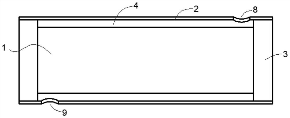
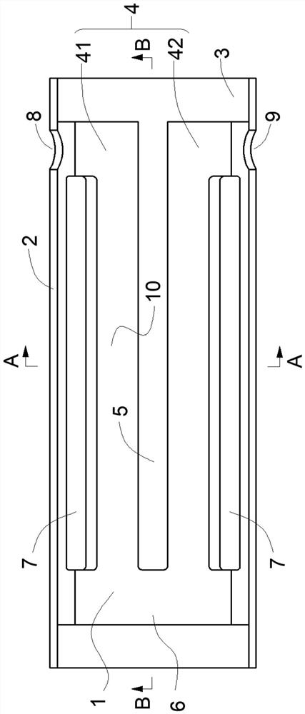
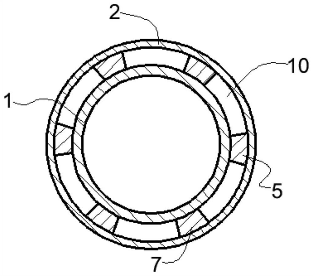
[0025] The gyrotron with a compact liquid cooling structure provided by the present invention includes a waveguide section 1 and a cooling tube 2 sleeved outside the waveguide section 1, flanges 3 are provided at both ends of the waveguide section 1, and the The liquid-tight fit between the flange 3 and the cooling pipe 2, between the flanges 3 at both ends, the cooling cavity 4 is formed from the outer wall of the waveguide section 1 to the inner wall of the cooling pipe 2, and the outer wall of the ...


PUM


Abstract

The invention discloses a gyrotron with a compact liquid-cooled structure, which belongs to the technical field of gyrotrons, and includes a waveguide section, a cooling cavity, and a cooling tube sleeved outside the waveguide section, and a partition bar is arranged on the outer wall of the waveguide section to separate the The bar extends axially along the waveguide section and divides the cooling cavity into a first cooling zone and a second cooling zone. The outlet and the liquid outlet are arranged at the same end of the cooling chamber, and the circumferential channel is arranged at the other end of the cooling chamber. The present invention changes the flow path of the cooling liquid by arranging the partition bar and the circumferential channel, and on the premise of avoiding the large-volume dead water area in the cooling chamber, the liquid outlet and the liquid inlet of the cooling chamber can be placed in the cooling chamber. The same end of the cavity, and the overall structure of the waveguide section in the radial direction maintains a compact single-layer structure.

Description

technical field [0001] The invention relates to the technical field of gyrotubes, in particular to gyrotubes provided with a compact liquid cooling structure. Background technique [0002] The gyrotron is an important high-power millimeter-wave and submillimeter-wave vacuum electronic device. Since the 1970s, driven by controlled nuclear fusion, millimeter-wave radar, high-energy physics and industrial applications, it has been used in various fields have achieved significant development. [0003] In the gyrotron system, the resonant cavity and the microwave output section are circular tube-shaped waveguide sections; these waveguide sections need to be cooled during high-power operation. At present, the existing gyrotron mainly has two liquid-cooled structures: [0004] The first is a single-layer liquid-cooled structure, such as figure 1 As shown, it mainly includes a waveguide section with flanges at both ends, a cooling tube sleeved outside the waveguide section, and a...

Claims


Application Information

Patent Timeline
Patent Type & Authority Patents(China)
IPC IPC(8): H01J7/24H01J5/02H01J23/12H01J25/02
CPCH01J5/02H01J7/24H01J23/12H01J25/02
Inventor 孙迪敏胡林林马国武卓婷婷张明君
Owner INST OF APPLIED ELECTRONICS CHINA ACAD OF ENG PHYSICS
Why Eureka
Try Eureka