
Multi-way reversing valve

A reversing valve and channel technology, applied in the field of reversing valves, can solve the problems of reducing extraction efficiency, multi-way reversing valves cannot use continuous extraction process, and increase extraction costs, so as to achieve the effect of improving extraction efficiency

Inactive Publication Date: 2015-02-11
JOFONT BIOTECH
View PDF5 Cites 0 Cited by
  • Summary
  • Abstract
  • Description
  • Claims
  • Application Information

AI Technical Summary

Problems solved by technology

However, the conventional multi-way reversing valve cannot be applied to the continuous extraction process, which reduces its application range
Furthermore, the design of the conventional multi-way reversing valve is relatively complicated, which may easily cause solvent leakage
[0004] In addition, because the conventional multi-way reversing valve cannot be used in the continuous extraction process, when the extraction process is performed, the extractant often has to be discharged from the system before reaching saturation, which increases the extraction cost and reduces the extraction efficiency

Method used


Image

  • Multi-way reversing valve
  • Multi-way reversing valve
  • Multi-way reversing valve

Examples


Embodiment Construction

[0040] The making and using of embodiments of the invention are discussed in detail below. It should be appreciated, however, that the embodiments provide many applicable inventive concepts that can be embodied in a wide variety of specific contexts. The specific embodiments discussed are illustrative only, and do not limit the scope of the invention.

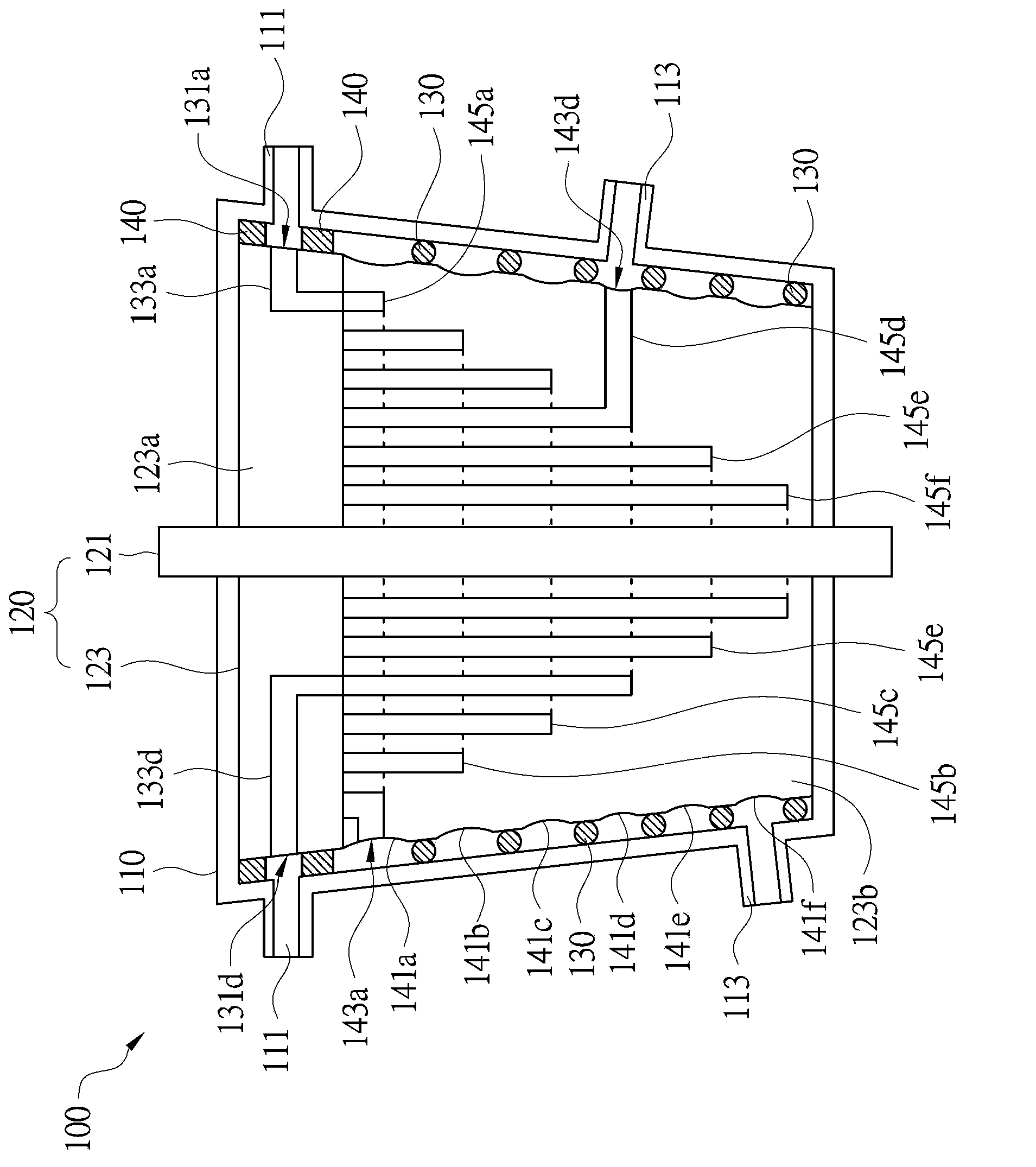
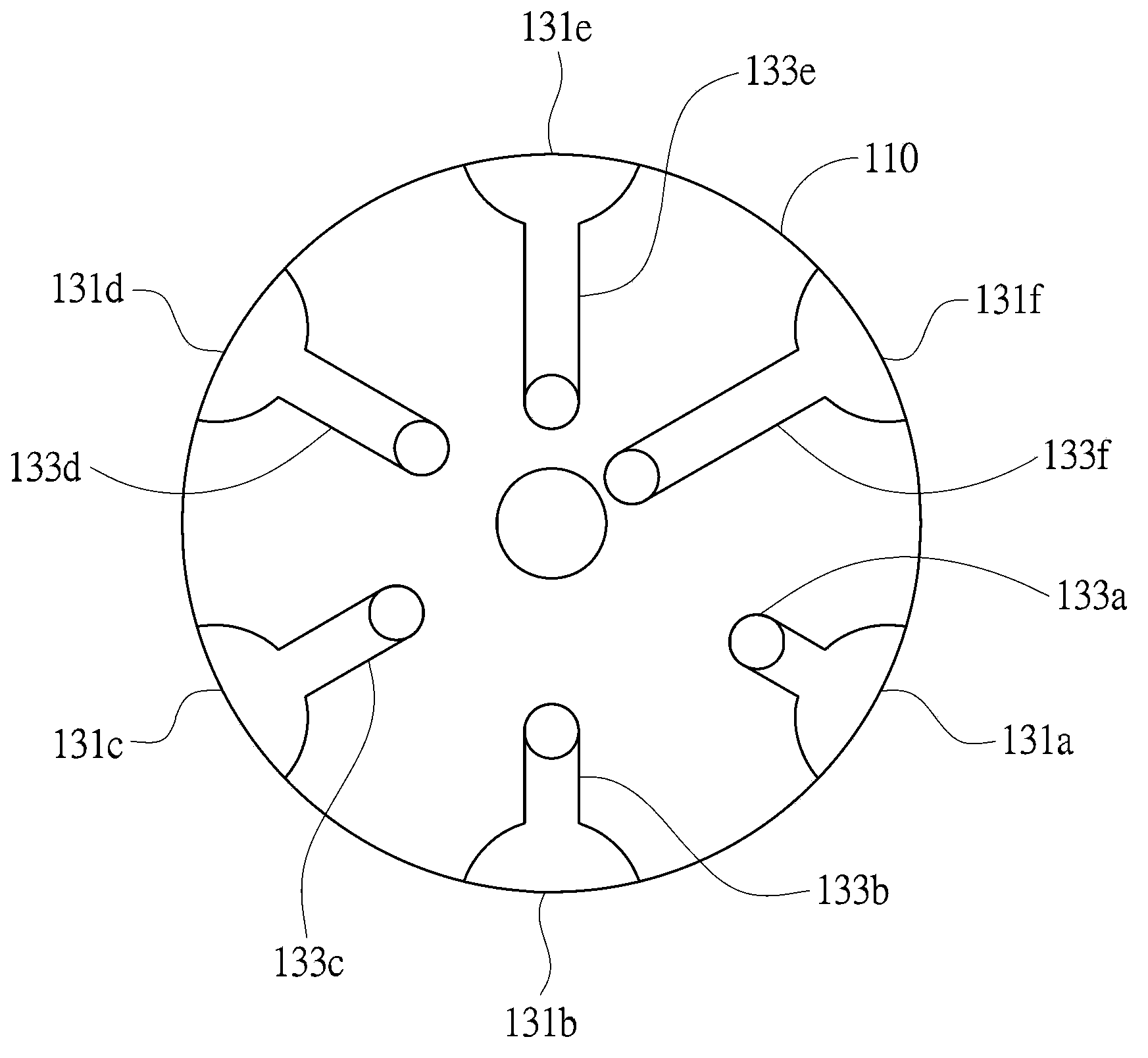
[0041] Please refer to Figures 1a to 1d ,in Figure 1a To illustrate a cross-sectional view of a multi-way reversing valve according to an embodiment of the present invention, Figure 1b A side view showing the structure of the rotary core of the multi-way reversing valve according to an embodiment of the present invention, Figure 1c drawn along Figure 1b A cross-sectional view of the input section cut by section line A-A, while Figure 1d to show along Figure 1b A top view of the output section taken along the middle section line B-B. In one embodiment, Figure 1a The multi-way reversing valve 100 includes a casing 1...


PUM


Abstract

The invention discloses a multi-way reversing valve. The multi-way reversing valve comprises a shell and a rotary core structure, wherein the shell is provided with at least three input pipelines and at least three output pipelines; the rotary core structure is assembled in the shell in a close fit way and comprises a connecting shaft and a body; the body is fixedly connected with the connecting shaft, is of an inversed circular truncated cone shape, and comprises an input part and an output part; the input part is arranged at the top end of the body and is provided with at least three inlets and at least three first channel structures communicated with the inlets in a one-to-one manner; the output part is arranged adjacent to the downside of the input part and comprises at least three circles of grooves and at least three second channel structures; the three circles of grooves are concentrically formed along the position, facing the downside of the body, on the connecting shaft; the diameters of the grooves are gradually reduced towards the downside of the body; each groove is provided with an outlet; the second channel structures are communicated with the outlets and the first channel structures in a one-to-one manner; the input pipelines are communicated with the inlets in a one-to-one manner and the output pipelines are communicated with the grooves in a one-to-one manner. During rotation, the connecting shaft drives the body to rotate together, and the flowing path of liquid can be changed.

Description

technical field [0001] The present invention relates to a reversing valve, and in particular to a multi-way reversing valve. Background technique [0002] In the common extraction or chromatography process, it is often necessary to use a storage tank with a large volume to store a variety of solvents to meet various extraction or chromatography processes. However, the complex process conditions and the order of adding solvents often make personnel make mistakes and cause industrial safety accidents. [0003] The general solution is to use a multi-way reversing valve to adjust the flow path of the solvent to simplify the operating conditions. However, the conventional multi-way reversing valve cannot be applied to the continuous extraction process, which reduces its application range. Furthermore, the design of the conventional multi-way reversing valve is relatively complicated, which may easily cause solvent leakage. [0004] In addition, since the conventional multi-way...

Claims


Application Information

Patent Timeline
Patent Type & Authority Applications(China)
IPC IPC(8): F16K11/08
CPCF16K11/083F16K27/062
Inventor 廖英崇吴耀军刘发宏
Owner JOFONT BIOTECH
Learn More