Installation method of flexible cables spanning string beams of existing buildings

A flexible cable and existing building technology, applied in construction, building maintenance, building construction, etc., can solve the problem of inappropriate installation method of the flexible cable for tensioned beams, reduce the difficulty of traction, improve the stability, and avoid friction damage Effect

Active Publication Date: 2020-11-27
BEIJING ACAD OF BUILDING ENG +2
View PDF5 Cites 0 Cited by
  • Summary
  • Abstract
  • Description
  • Claims
  • Application Information

AI Technical Summary

Problems solved by technology

The current installation methods of string beam flexible cables are not applicable

Method used


Image

  • Installation method of flexible cables spanning string beams of existing buildings
  • Installation method of flexible cables spanning string beams of existing buildings
  • Installation method of flexible cables spanning string beams of existing buildings

Examples


Embodiment Construction

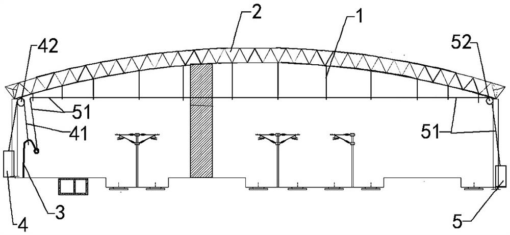
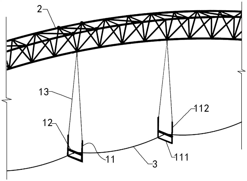
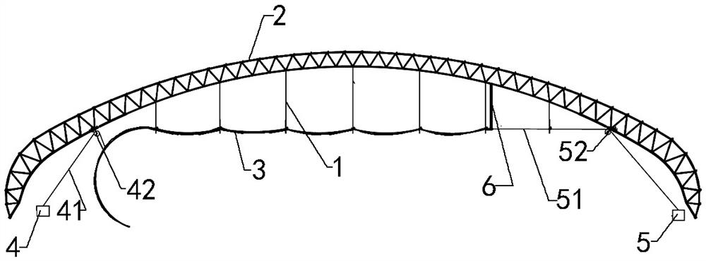
[0043] Such as Figure 1 to Figure 2 As shown, the installation structure of the string beam flexible stay cable spanning the existing buildings of the present invention includes a pulley slide device 1 suspended under the upper string girder 2, a hoist hoist 4 for vertically lifting the stay cable body 3, and a hoisting hoist 4 for horizontal The traction hoist 5 for pulling the cable body 3 and the cable body 3 passing through the pulley cable device 1 .

[0044] The pulley cable device 1 is arranged at intervals along the direction of the upper chord main beam 2. The pulley cable device 1 is as close as possible to the strut of the string beam. The distance between adjacent pulley cable devices 1 needs to be determined according to the calculated simulation model. The simulation model is based on The sag of the cable body 3 under its own weight is greater than the requirement of the safety distance of the existing building, and the construction process simulation model of t...


PUM


Abstract

The invention relates to the technical field of beam string structure construction, and discloses a mounting structure and method for a beam string structure flexible cable spanning existing buildings. The mounting structure comprises pulley sliding cable devices which are hung below an upper chord main beam, a lifting device used for vertically lifting a cable body, and a traction device used forhorizontally pulling the cable body; the pulley sliding cable devices are arranged at intervals in the direction of the upper chord main beam and comprise U-shaped hanging frames, rotating supportingrods in the U-shaped hanging frames, and guide chains connected with the U-shaped hanging frames and the upper chord main beam; the rotating supporting rods are rotationally connected with the U-shaped hanging frames, and the cable body is erected on the rotating supporting rods. The lifting device comprises a lifting winch, a first steering pulley arranged on the top of an upright column, and alifting rope; the traction device comprises a traction winch, a second steering pulley at the top of the upright column, and a traction rope. The mounting structure does not occupy many ground construction sites, requirements for the construction environment are low, and the influence on the construction sites is small.

Description

technical field [0001] The invention relates to the technical field of string beam construction, in particular to a method for installing flexible cables of string beams spanning existing buildings. Background technique [0002] The string beam structure is an efficient large-span space steel structure based on the concept of tension as a whole. The installation methods of the flexible cables at the lower part can be roughly divided into two types. One is to combine steel structures, braces and prestressed cables. After the ground assembly is completed, the whole is hoisted, lifted, jacked up or slipped into place, and finally stretched; the other is that the steel structure in the string beam structure has been assembled at a high altitude on the tire frame, and the cables are deployed on the ground. After that, through mechanical traction, it is connected with the struts and ear plates, and finally stretched. [0003] In addition to the construction of new factory buildin...

Claims


Application Information

Patent Timeline
Patent Type & Authority Patents(China)
IPC IPC(8): E04G23/02
CPCE04G23/02
Inventor 司波陈志华鲍敏刘红波尤德清兰春光高晋栋左安位张东孙善星袁英占尧金金张致豪王丰周黎光马睿唐涛张锐杨明哲
Owner BEIJING ACAD OF BUILDING ENG
Why Eureka
Try Eureka