Eureka AIR delivers breakthrough ideas for toughest innovation challenges, trusted by R&D personnel around the world.

Cutting device with laser level meter

A technology of laser level meter and cutting device, which is applied in the direction of auxiliary devices, welding/cutting auxiliary equipment, gas flame welding equipment, etc., which can solve the problems of affecting cutting quality, labor waste, and waste debris scattering, so as to improve cutting quality and save labor Cost, the effect of saving cutting cost

Inactive Publication Date: 2019-03-19
四川缘福科技有限公司
View PDF0 Cites 6 Cited by
  • Summary
  • Abstract
  • Description
  • Claims
  • Application Information

AI Technical Summary

Problems solved by technology

The above-mentioned cutting device has certain disadvantages in the cutting function, because the shape of the material is different, when it needs to be cut horizontally, if the line is drawn manually, it will cause a waste of labor, and the accuracy of the line draft cannot be guaranteed, and the cutting will cause The waste will be scattered on the surface of the workbench, affecting the normal use of the cutting device and affecting the cutting quality, and the existing cutting device uses electromagnetic clamps to fix the cutting material, which costs a lot. Therefore, we propose a belt Cutting unit with laser level

Method used


Image

  • Cutting device with laser level meter
  • Cutting device with laser level meter

Examples


Embodiment Construction

[0020] In order to make the purpose, technical solution and advantages of the present invention clearer, the technical solution of the present invention will be described in detail below. Apparently, the described embodiments are only some of the embodiments of the present invention, but not all of them. Based on the embodiments of the present invention, all other implementations obtained by persons of ordinary skill in the art without making creative efforts fall within the protection scope of the present invention.

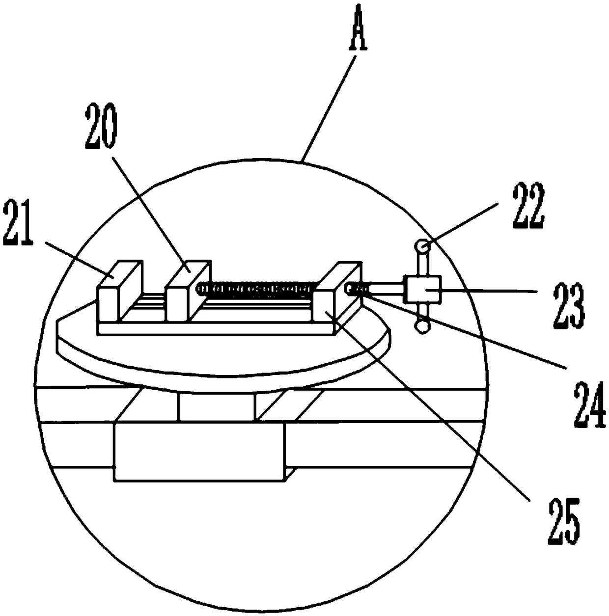
[0021] see Figure 1-Figure 2 As shown, the invention provides a cutting device with a laser level, comprising:

[0022] A workbench 1, the upper surface of the workbench 1 is provided with a first slide rail 2 and a second slide rail 3 in parallel, and the connection between the inner sides of the two ends of the first slide rail 2 and the second slide rail 3 and the workbench 1 Limiting blocks 18 are all provided, the first linear motor 4 is installed on the...


PUM


Abstract

The invention discloses a cutting device with a laser level meter. The cutting device comprises a working table and a mechanical fixture. A first sliding rail and a second sliding rail are arranged onthe upper surface of the working table in a parallel mode. Limiting blocks are arranged at the connecting positions between the inner sides of two ends of the first sliding rail and the second sliding rail and the working table. A first linear motor is mounted on the surface of the first sliding rail. A sliding block is mounted on the surface of the second sliding rail. A first linear motor is connected with a supporting rod by the sliding block. A second linear motor is connected to the supporting rod in a sleeving mode. A rotating motor is mounted at the second linear motor. A tray is fixedly connected to the output shaft of the rotating motor. The mechanical fixture is fixedly mounted on the upper surface of the tray. The cutting device has the beneficial effects that an electromagnetic fixture is replaced with the mechanical fixture, the cutting cost is saved, an arranged dust collecting plate can collect and process scraps produced by cutting in time, the mounted laser level meter can improve the accuracy rate of lining, and the cutting quality is guaranteed.

Description

technical field [0001] The invention relates to the field of cutting devices, in particular to a cutting device with a laser level. Background technique [0002] As a cutting tool, the traditional cutting machine has a wide range of applications and can be used to cut metal or non-metal materials, and the cutting is fast and convenient. A traditional cutting machine generally includes a workbench, a linear motor and a rotary motor are located above the workbench, and a slide rail device is installed on the upper surface of the workbench, and a bracket is provided on the outside of the slide rail. torch. The above-mentioned cutting device has certain disadvantages in the cutting function, because the shape of the material is different, when it needs to be cut horizontally, if the line is drawn manually, it will cause a waste of labor, and the accuracy of the line draft cannot be guaranteed, and the cutting will cause The waste will be scattered on the surface of the workben...

Claims


Application Information

Patent Timeline
Patent Type & Authority Applications(China)
IPC IPC(8): B23K7/00B23K7/10B23K37/02B23K37/04B23K37/047
CPCB23K7/00B23K7/10B23K37/0252B23K37/0435B23K37/047
Inventor 何君豪
Owner 四川缘福科技有限公司
Why Eureka
Eureka Blog
Learn More