High-pressure quick joint for high-pressure gas storage and transportation equipment

A high-pressure gas and equipment technology, which is applied in the field of quick connection between bulk gas storage and transportation equipment and process systems, can solve problems such as difficult processing and manufacturing, complex structure of locking devices, and high price

Inactive Publication Date: 2019-03-15
CHINA PETROLEUM & CHEM CORP +1
View PDF10 Cites 1 Cited by
  • Summary
  • Abstract
  • Description
  • Claims
  • Application Information

AI Technical Summary

Problems solved by technology

[0004] The locking and locking device of the quick joint has a complex structure, requires very high matching accuracy, is difficult to process, and is not easy to process and manufacture. This is one of the reasons for the high price of this product; in addition, the strength and reliability of this connection are difficult to pass. Determination by conventional methods usually requires the use of finite element analysis for design, which is also a factor that makes it expensive, especially for customized products

Method used


Image

  • High-pressure quick joint for high-pressure gas storage and transportation equipment
  • High-pressure quick joint for high-pressure gas storage and transportation equipment
  • High-pressure quick joint for high-pressure gas storage and transportation equipment

Examples


Embodiment Construction

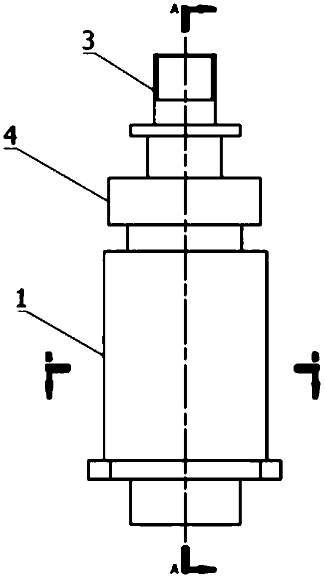
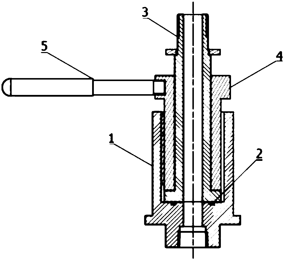
[0038] The specific implementation manners of the embodiments of the present invention will be further described in detail below in conjunction with the drawings and embodiments. The following examples are used to illustrate the embodiments of the present invention, but are not intended to limit the scope of the embodiments of the present invention.

[0039] In the description of the embodiments of the present invention, it should be noted that the terms "center", "longitudinal", "transverse", "upper", "lower", "front", "rear", "left", "right" , "vertical", "horizontal", "top", "bottom", "inner", "outer" and other indicated orientations or positional relationships are based on the orientations or positional relationships shown in the drawings, and are only for the convenience of describing the present invention The embodiments and simplified descriptions do not indicate or imply that the devices or elements referred to must have a specific orientation, be constructed and opera...


PUM


Abstract

The invention relates to the field of quick joints and discloses a high-pressure quick joint for high-pressure gas storage and transportation equipment. The high-pressure quick joint comprises a jointbody, a shouldered joint pipe and a sleeve pipe. The joint body is a hollow column with one end open. The upper end of the joint body is provided with an axial inner hole. The bottom of the joint body is provided with a first connecting pipe hole communicating with the axial inner hole. An annular sealing ring is arranged on the bottom surface of the axial inner hole. An annular outer shoulder isarranged on the periphery of the lower end of the shouldered joint pipe. The shouldered joint pipe is plugged into the joint body along the axial inner hole to be in sealing connection with the bottom surface of the axial inner hole. The shouldered joint pipe is sleeved with the sleeve pipe. The lower end face of the sleeve pipe is clamped and pressed on the upper surface of the annular outer shoulder. A plurality of spaced internal threads are machined on the inner wall of the axial inner hole in the circumferential direction. The periphery of the sleeve pipe is provided with a plurality ofexternal threads matched with the internal threads. A limiting check ring is arranged on the upper middle portion of the shouldered joint pipe. Through the high-pressure quick joint, quick connectioncan be realized quickly. All the pressure bearing components adopt the conventional structure form. The high-pressure quick joint is simple in design and high in reliability.

Description

technical field [0001] Embodiments of the present invention relate to the technical field of quick connection between bulk gas storage and transportation equipment and process systems, and in particular to a high-pressure quick connector used on high-pressure gas storage and transportation equipment. Background technique [0002] At present, bulk gas is usually transported in the form of high-pressure gas cylinder containers and high-pressure long-tube trailers. The main valve of high-pressure gas cylinder containers basically adopts conventional gas cylinder valves, so the connection method of the process system is still the original connection. Joints and fixtures for gas cylinder valves; since the diameter of conventional gas cylinder valves is only 4mm, it cannot meet the process conditions with high flow rates. The connection between the high-pressure long pipe trailer and the process system usually adopts a special high-pressure quick connector for high-pressure gas st...

Claims


Application Information

Patent Timeline
Patent Type & Authority Applications(China)
IPC IPC(8): F16L15/04F16L15/06F16L33/18F17C13/00
CPCF16L15/04F16L15/06F16L33/18F17C13/002F17C2205/037
Inventor 王群
Owner CHINA PETROLEUM & CHEM CORP
Why Eureka
Try Eureka