
Industrial robot geometric parameter identification method based on transformation matrix error model

An industrial robot and transformation matrix technology, applied in manipulators, manufacturing tools, program-controlled manipulators, etc., can solve the problems of production line production capacity and efficiency, and achieve the goal of improving end positioning accuracy, measurement accuracy, and efficiency. Effect

Active Publication Date: 2019-03-15
NANJING INST OF TECH
View PDF7 Cites 11 Cited by
  • Summary
  • Abstract
  • Description
  • Claims
  • Application Information

AI Technical Summary

Problems solved by technology

The above three calibration methods are all offline calibration. The industrial robot needs to stop the current task, and even needs to move the industrial robot from the production line to enter the corresponding calibration procedure, which has a great impact on the production capacity and efficiency of the production line.

Method used


Image

  • Industrial robot geometric parameter identification method based on transformation matrix error model
  • Industrial robot geometric parameter identification method based on transformation matrix error model
  • Industrial robot geometric parameter identification method based on transformation matrix error model

Examples


Embodiment Construction

[0036] The present invention is described in further detail now in conjunction with accompanying drawing.

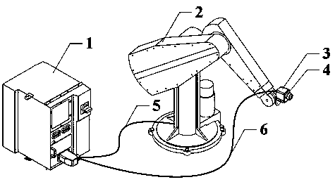
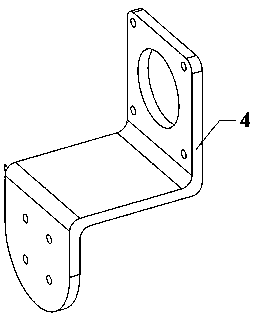
[0037] Such as figure 1 and figure 2 As shown, a method for identifying geometric parameters of an industrial robot based on a transformation matrix error model. The structure of an industrial robot includes a robot control cabinet 1, an industrial robot 2, an intelligent industrial camera 3, a camera mounting frame 4, a control signal communication cable 5 and a transmission signal communication Cable 6, the intelligent industrial camera 3 is fixedly installed at the end of the industrial robot 2 through the camera mounting frame 4, the industrial robot 2 is connected to the robot control cabinet 1 through the control signal communication cable 5, and the intelligent industrial camera 3 It is connected with the robot control cabinet 1 through the signal transmission communication cable 6 .

[0038] In this embodiment, a processor capable of processing and sending sig...


PUM


Abstract

The invention relates to an industrial robot geometric parameter identification method based on a transformation matrix error model, wherein the industrial robot structure comprises a robot control cabinet, an industrial robot, a smart industrial camera, a camera mount, a control signal communication cable and a transmission signal communication cable. The industrial robot geometric parameter identification method first establishes the transformation matrix error model of the industrial robot, and secondly, obtains the tail end pose nominal transformation matrix of the industrial robot and thetail end pose actual transformation matrix of the industrial robot, finally, obtains a geometric parameter error by substituting the nominal transformation matrix and the actual transformation matrixinto the transformation matrix error model, and inputs the geometric parameter error into the robot control cabinet to adjust the positioning accuracy of the tail end of the industrial robot. This method eliminates the need for expensive external measuring equipment and eliminates the need for additional calibration to increase the efficiency, productivity and automation of industrial lines.

Description

technical field [0001] The invention relates to the technical field of industrial robot parameter calibration, in particular to a method for identifying geometric parameters of industrial robots based on a transformation matrix error model. Background technique [0002] As a representative of intelligent manufacturing equipment, industrial robots are the focus of high-end manufacturing development, and their R&D, manufacturing and application have become an important indicator of a country's technological innovation level. With the rapid development of robot technology, the application fields of industrial robots are also expanding, such as hole making and riveting in the aerospace industry. These applications have higher and higher precision requirements for industrial robots. At present, the repetitive positioning accuracy of industrial robots can reach as high as ±0.02mm, but the absolute accuracy is generally low, generally a few millimeters or even higher. [0003] The...

Claims


Application Information

Patent Timeline
Patent Type & Authority Applications(China)
IPC IPC(8): B25J9/16
CPCB25J9/1664
Inventor 乔贵方张腾飞孙大林温秀兰芮平张颖王东霞
Owner NANJING INST OF TECH
Learn More