Eureka AIR delivers breakthrough ideas for toughest innovation challenges, trusted by R&D personnel around the world.

Rhythmic vacuum purification nitrogen protection brazing furnace

A technology of vacuum purification and nitrogen protection, which is applied in welding equipment, auxiliary devices, metal processing, etc., can solve the problems of high brazing quality, high use cost, and difficult technology to achieve, and achieve high brazing quality and brazing The effect of high welding efficiency

Inactive Publication Date: 2019-03-12
江苏韦斯泰科技有限公司
View PDF7 Cites 1 Cited by
  • Summary
  • Abstract
  • Description
  • Claims
  • Application Information

AI Technical Summary

Problems solved by technology

The continuous nitrogen shielded brazing furnace can be used for mass production of aluminum heat exchangers, which can obtain higher economic benefits, but the products produced in this way cannot meet the higher requirements for brazing quality, and the aluminum brazing temperature is generally at At around 577°C, the requirement for the oxygen concentration in the brazing environment is not higher than 50ppm. The lower the oxygen concentration, the better the brazing quality, but it is difficult to achieve it with the existing technology
[0003] In addition, in the field of brazing of aluminum heat exchangers, vacuum brazing furnaces are also widely used. Vacuum brazing furnaces can obtain higher brazing quality, but the aluminum heat And then lower the temperature to room temperature. This process is completed in the furnace of the vacuum brazing furnace. The heat cannot be recycled, and the energy consumption is quite large, which makes the use cost too high
[0004] Summarize the shortcomings of the above two prior art as follows: 1. The quality of brazing is average; 2. The heat cannot be recycled, the loss is too large, and the cost is too high; 3. The oxygen concentration of the brazing environment cannot meet the requirements

Method used


Image

  • Rhythmic vacuum purification nitrogen protection brazing furnace

Examples


Embodiment Construction

[0019] In order to describe the technical content, structural features, goals and effects of the present invention in detail, the following examples are given to describe the embodiments in conjunction with the accompanying drawings.

[0020] In describing the present invention, it is to be understood that the terms "central", "longitudinal", "transverse", "front", "rear", "left", "right", "vertical", "horizontal", The orientations or positional relationships indicated by "top", "bottom", "inner", "outer", etc. are based on the orientations or positional relationships shown in the drawings, and are only for the convenience of describing the present invention and simplifying the description, rather than indicating or implying The devices or elements referred to must have a specific orientation, be constructed and operate in a specific orientation, and therefore should not be construed as limiting the scope of the invention.

[0021] The present invention provides a rhythmic vac...


PUM


Abstract

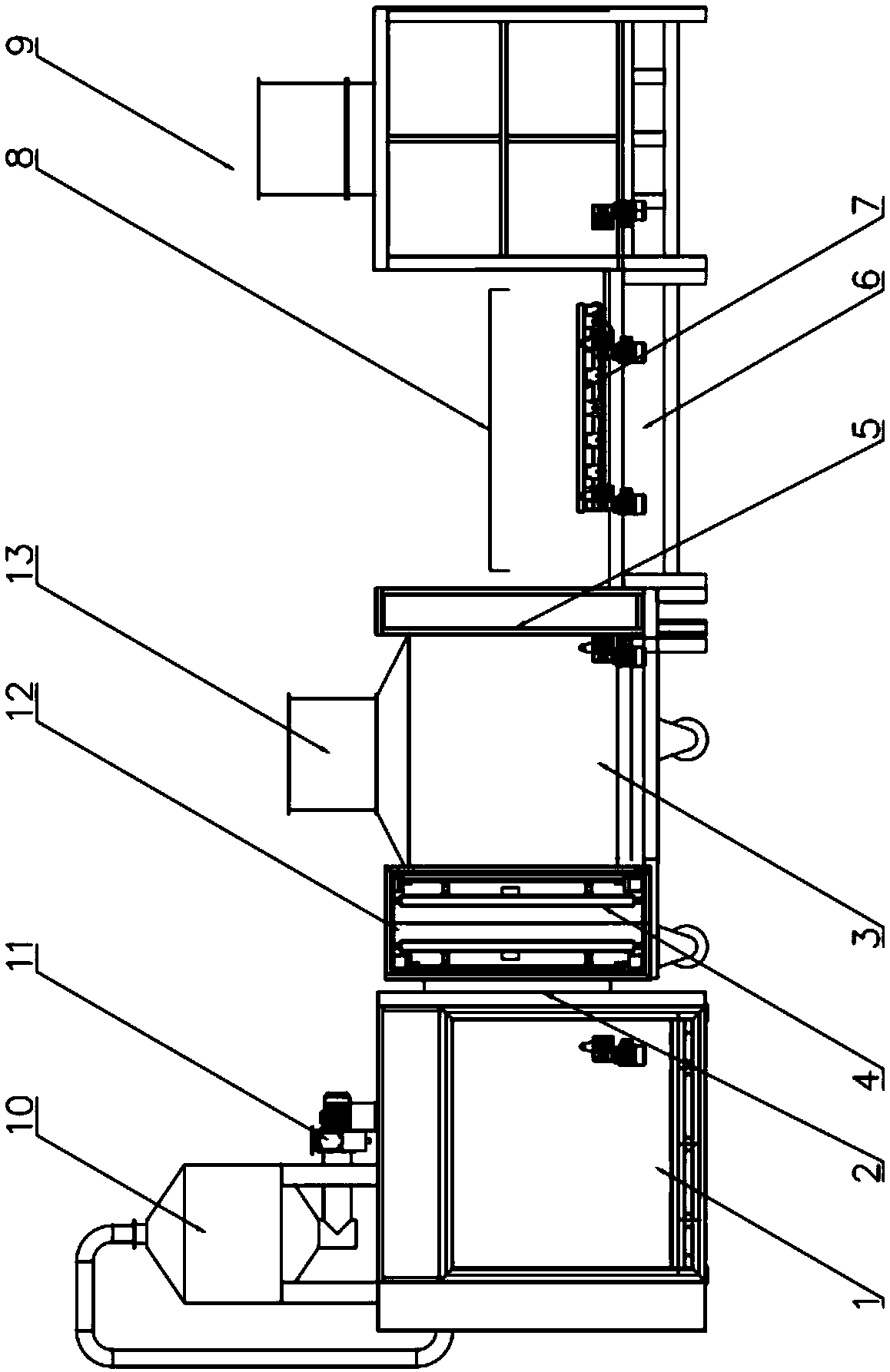
The invention provides a rhythmic vacuum purification nitrogen protection brazing furnace which comprises a brazing chamber, a guide rail and a control panel. A thermostat is arranged in the brazing chamber; an access port is formed in the side surface of the brazing chamber; a vacuum purification chamber is connected to the access port of the brazing chamber; openings are formed in two sides of the vacuum purification chamber; a first furnace door is arranged between the opening close to the brazing chamber and the access port; a second furnace door is arranged on the opening far away from the brazing chamber; a nitrogen filling pipeline is further arranged in the vacuum purification chamber; the guide rail is used for connecting the brazing chamber and the vacuum purification chamber; aconveying vehicle for conveying a product is slidably connected onto the guide rail and is connected with a drive device; the guide rail extends out of the second furnace door and forms a feeding andblanking area; an air cooling device is further arranged beside the feeding and blanking area; and the control panel is used for controlling the devices. The rhythmic vacuum purification nitrogen protection brazing furnace provided by the invention has the advantages of high brazing quality and the like.

Description

technical field [0001] The invention relates to the technical field of flux pre-coating, in particular to a rhythmic vacuum purification nitrogen protection brazing furnace. Background technique [0002] The brazing furnaces in the prior art generally include two types: continuous nitrogen shielded brazing furnaces and vacuum brazing furnaces. The continuous nitrogen shielded brazing furnace can be used for mass production of aluminum heat exchangers, which can obtain higher economic benefits, but the products produced in this way cannot meet the higher requirements for brazing quality, and the aluminum brazing temperature is generally at At about 577°C, the requirement for the oxygen concentration in the brazing environment is not higher than 50ppm. The lower the oxygen concentration, the better the brazing quality, but it is difficult to achieve it with the existing technology. [0003] In addition, in the field of brazing of aluminum heat exchangers, vacuum brazing furna...

Claims


Application Information

Patent Timeline
Patent Type & Authority Applications(China)
IPC IPC(8): B23K3/00B23K3/08B23K1/008
CPCB23K1/008B23K3/00B23K3/08
Inventor 王伟
Owner 江苏韦斯泰科技有限公司
Why Eureka
Eureka Blog
Learn More