
A Fast Scanning Exposure Method Based on DMD Flat State

A technology of fast scanning and exposure methods, which is applied in microlithography exposure equipment, photolithography exposure devices, optics, etc., can solve the problems that affect the productivity of scanning exposure systems, affect the scanning speed, etc., and increase the scanning step length , Improve scanning speed and productivity, and reduce the effect of line width difference

Active Publication Date: 2021-03-05
HEFEI CHIP FOUND MICROELECTRONICS EQUIP CO LTD
View PDF8 Cites 0 Cited by
  • Summary
  • Abstract
  • Description
  • Claims
  • Application Information

AI Technical Summary

Problems solved by technology

The line width difference of the lines in different directions limits the increase of the scanning step size, and a smaller scanning step size requires a higher DMD refresh frequency, which affects the improvement of the scanning speed and ultimately affects the performance of the scanning exposure system. Increased production capacity

Method used


Image

  • A Fast Scanning Exposure Method Based on DMD Flat State
  • A Fast Scanning Exposure Method Based on DMD Flat State
  • A Fast Scanning Exposure Method Based on DMD Flat State

Examples


Embodiment Construction

[0028] In order to make the purpose, technical solutions and advantages of the embodiments of the present invention clearer, the technical solutions in the embodiments of the present invention will be clearly and completely described below in conjunction with the drawings in the embodiments of the present invention. Obviously, the described embodiments It is a part of embodiments of the present invention, but not all embodiments.

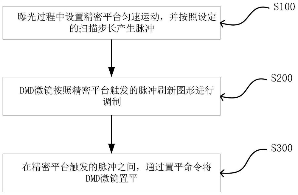
[0029] Such as figure 1 As shown, the fast scanning exposure method based on the DMD flat state described in this embodiment includes the following steps:

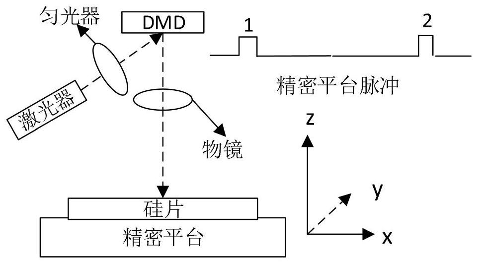
[0030] S100, the precision platform moves at a constant speed, and generates pulses according to a certain scanning step;

[0031] S200 and DMD refresh the graphics according to the pulse triggered by the precision platform;

[0032] S300. Leveling the DMD micromirror through a leveling command between pulses triggered by the precision platform.

[0033] The specific embodiment of the present...


PUM


Abstract

A fast scanning exposure method based on DMD leveling state of the present invention can solve the technology that the "smear" in scanning exposure affects the improvement of scanning step length, and then affects the scanning speed and productivity of scanning exposure system question. It includes the following steps: S100, setting the precision platform to move at a constant speed during the exposure process, and generating pulses according to the set scanning step; S200, modulating the DMD micromirror according to the pulse refresh pattern triggered by the precision platform S300, after the pulses triggered by the precision platform During this period, set the DMD micromirror through the leveling command. The fast scanning exposure method based on the DMD leveling state of the present invention reduces the influence of "smear" on the line width difference of lines with the same line width in different directions by leveling the DMD micromirror between two precision platform pulses , and can greatly increase the scan step size and reduce the requirement for DMD refresh frequency, thereby improving scan speed and productivity.

Description

technical field [0001] The invention relates to the technical field of laser maskless lithography, in particular to a fast scanning exposure method based on a flat state of a DMD. Background technique [0002] Based on laser maskless lithography, also known as laser direct imaging (Laser Direct Imaging, LDI), it is a technology that uses a spatial light modulator (Spatial Light Modulator, SLM) to transfer the exposure pattern to the photoresist for imaging. [0003] As a kind of spatial light modulator, digital micromirror DMD (Digital Micro mirror Device) is widely used in maskless lithography system. It is an array of micromirrors, whose micromirrors are independently controlled by the CMOS memory below them, and correspond to a pixel in the image. When the data in the CMOS memory is 1, the micromirror deflects +12 degrees, corresponding to the open state; when the data in the CMOS memory is 0, the micromirror deflects -12 degrees, corresponding to the off state. In addi...

Claims


Application Information

Patent Timeline
Patent Type & Authority Patents(China)
IPC IPC(8): G03F7/20
CPCG03F7/2053G03F7/704G03F7/2057
Inventor 卞洪飞赵美云
Owner HEFEI CHIP FOUND MICROELECTRONICS EQUIP CO LTD
Learn More