
Laser coaxiality detection device and method

A detection device and coaxiality technology, which is applied in the direction of measuring devices, optical devices, instruments, etc., can solve the problems of undeveloped sensor products, increased cost needs, and large subjective errors, etc., so as to facilitate computer analysis, simple and practical cost, and Effect of reducing measurement error

Pending Publication Date: 2019-03-08
北京国泰蓝盾科技有限公司
View PDF0 Cites 8 Cited by
  • Summary
  • Abstract
  • Description
  • Claims
  • Application Information

AI Technical Summary

Problems solved by technology

[0003] In engineering, the detection of the coaxiality of the laser beam combination mainly adopts the method of long-distance laser shooting, and the whole set of devices is moved to a larger field of vision. Laser beam detection, this kind of detection has high requirements on the field environment, and requires more operators, monitors and other detection devices, low flexibility and complicated operation
In addition, the collimated light tube method can be used in the laboratory. The light of different spectra passes through the collimated light tube and is focused on the focal plane. Use photo paper to observe the position of the spot. This method has a large subjective error. Instead of photoelectric conversion imaging devices such as cameras, subjective errors can be eliminated by measuring spot images, but there are no mature products for simultaneous imaging of visible light to long-wave infrared bands. The need has increased dozens of times

Method used


Image

  • Laser coaxiality detection device and method
  • Laser coaxiality detection device and method
  • Laser coaxiality detection device and method

Examples

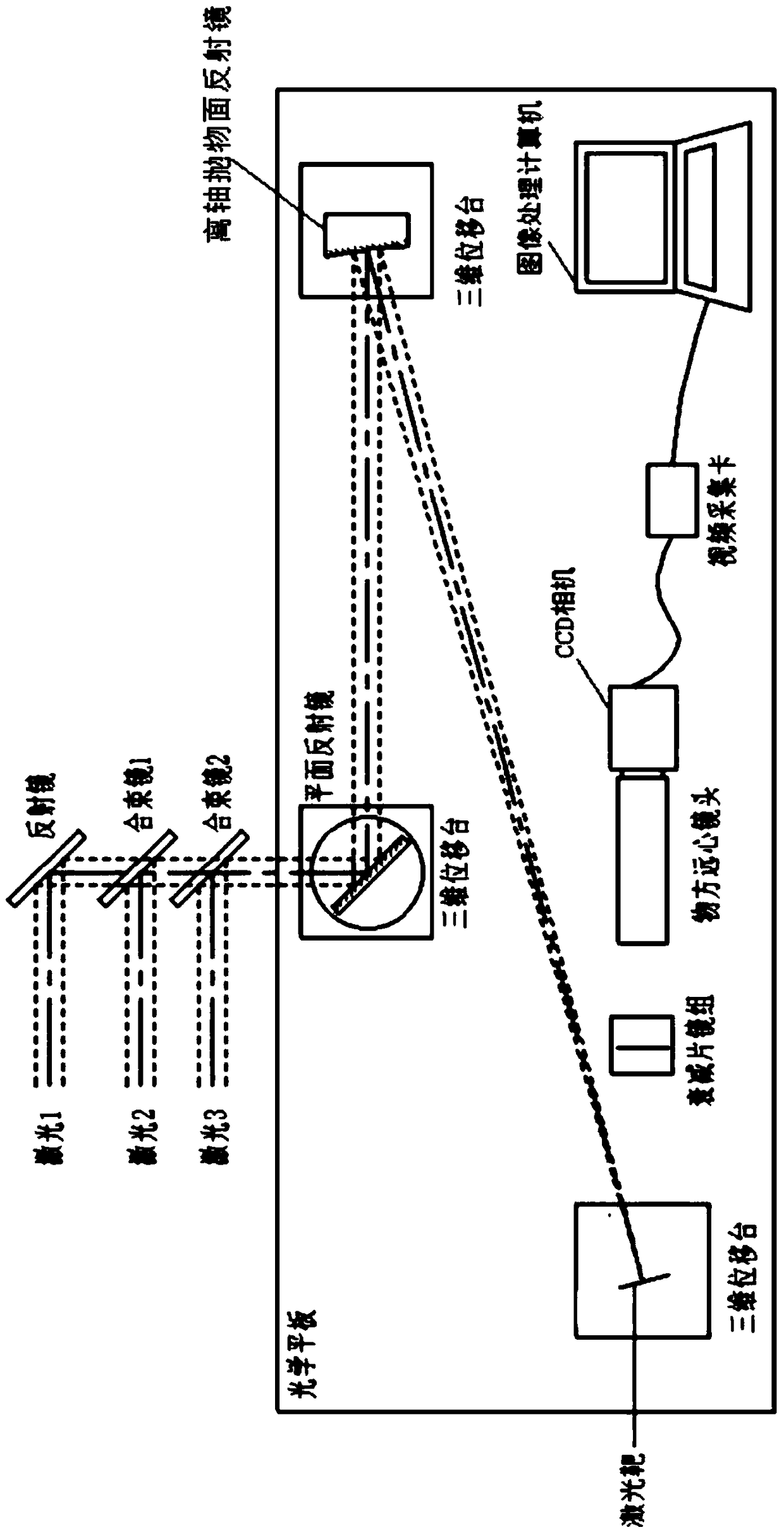

Embodiment Construction

[0025] The following will clearly and completely describe the technical solutions in the embodiments of the present invention with reference to the accompanying drawings in the embodiments of the present invention. Obviously, the described embodiments are only some, not all, embodiments of the present invention. All other embodiments obtained by persons of ordinary skill in the art based on the embodiments of the present invention belong to the protection scope of the present invention.

[0026] According to an embodiment of the present invention, a laser coaxiality detection device is provided.

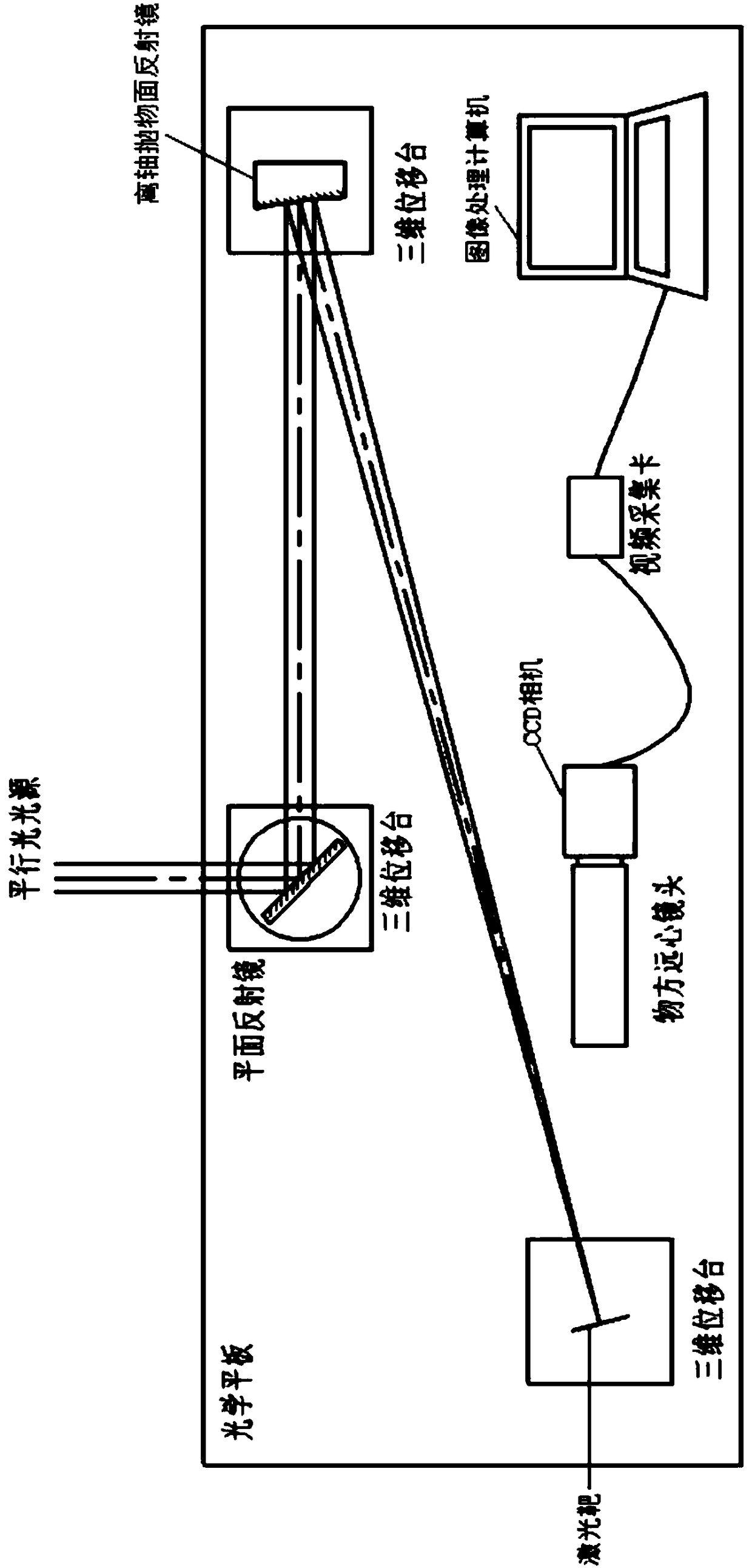
[0027] Such as figure 1 As shown, the laser coaxiality detection device according to the embodiment of the present invention includes a measuring device, and the measuring device includes: an off-axis parabolic reflector, a laser target, an object telecentric lens, a CCD camera, an image processing computer; an off-axis parabolic reflector The mirror is used to converge the incident...


PUM


Abstract

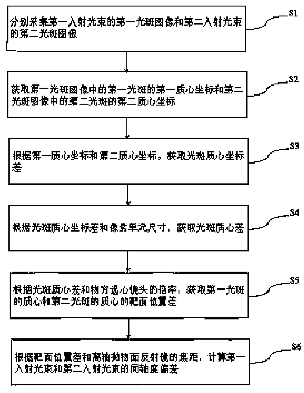
The invention discloses a laser coaxiality detection device and method. The laser coaxiality detection device comprises an off-axis parabolic reflector, a laser target, an object side telecentric lens, a CCD camera, and an image processing computer; the off-axis parabolic reflector is used for concentrating an incident beam to obtain a concentrated beam, and transmitting the concentrated beam to the laser target; the laser target placed at the focus position of the off-axis parabolic reflector is used for receiving the concentrated beam to form a spot; and the CCD camera provided with the object side telecentric lens is used for photographing the target surface of the laser target so as to acquire a spot image; and the image processing computer is used for processing the spot image. With the above technical schemes of the present invention adopted, the laser coaxiality detection device and method can meet measurement accuracy requirements, and has the advantages of low cost and simplepracticality.

Description

technical field [0001] The present disclosure relates to the field of optoelectronic technology, in particular to a laser coaxiality detection device and a method thereof. Background technique [0002] The general characteristics of the photoelectric countermeasure system are to start interference or damage lasers, to carry out interference or damage to the target in a specific band, and to conduct full-band non-selective emission for infrared band detectors or visible light band TVs. One machine is multi-functional and integrated high degree. The multi-spectral laser beams are combined and output from the exit window, with a common aperture and coaxial emission, while ensuring that each beam of laser light can still illuminate the same target at the same time during long-distance use. Multi-spectral beam combining is one of the key technologies in the development of this type of system. The coaxiality accuracy of each laser optical axis after beam combining is one of the n...

Claims


Application Information

Patent Timeline
Patent Type & Authority Applications(China)
IPC IPC(8): G01B11/27
CPCG01B11/272
Inventor 张艳茹王皓段海峰
Owner 北京国泰蓝盾科技有限公司
Learn More