
Exerting device for I-beam prestressing

A technology of applying device and I-beam, which is applied in the processing of building materials, construction, building construction, etc., can solve the problems of the limitation of the applied prestress, the inability to use, and the high linearity requirements of prestressed steel bars, so as to improve the tensioning efficiency. , flexible use, good seismic performance

Pending Publication Date: 2019-03-08
NINGBO UNIV
View PDF0 Cites 4 Cited by
  • Summary
  • Abstract
  • Description
  • Claims
  • Application Information

AI Technical Summary

Problems solved by technology

The construction process of the pre-bending method is simple, but in the process of restoring the reverse arch of the wooden beam, the prestress established is slightly smaller than the prestress directly applied to the wooden beam, so it cannot be used in projects that require a large prestress. , the pre-bending method requires a higher strength adhesive
The linearity of the prestressed steel bar is high in the wire tensioning method, and it is difficult to use it when the diameter of the steel bar is large, and the partial pressure problem at the beam end and the inflection point of the steel bar also limits the promotion of the perforated wire threading method
The prestressed bamboo and wooden beams can form a composite structure through the end tension method, and the appearance is better, but due to the partial pressure at the end and the shear resistance of the rollers, the amount of prestress applied will be limited
The web extension method produces an upward concentrated force at the web, which makes the application of prestress better, but this increases the cross-sectional height of the beam and limits the available space of the structure

Method used


Image

  • Exerting device for I-beam prestressing
  • Exerting device for I-beam prestressing
  • Exerting device for I-beam prestressing

Examples


Embodiment Construction

[0021] The present invention will be further described in detail below in conjunction with the accompanying drawings and embodiments.

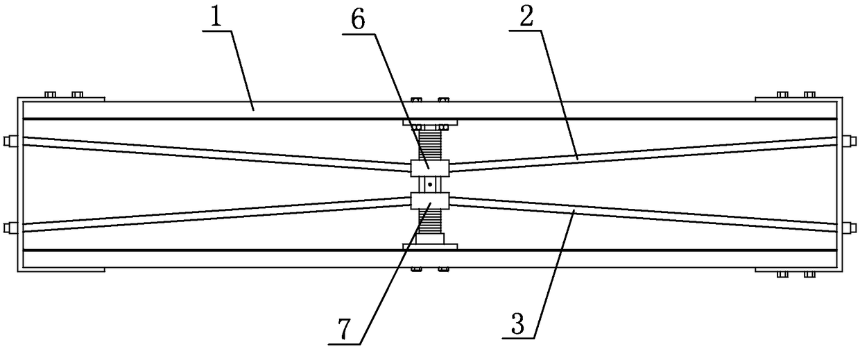
[0022] As shown in the figure, a device for applying I-beam prestress includes two-way tension mechanisms arranged in the flanges on both sides of I-beam 1. The two-way tension mechanism is located in the middle of I-beam 1, and each The upper steel strand 2 and the lower steel strand 3 are arranged in the side flange, and the two ends of the I-beam 1 are respectively fixed with the connecting plate 4, and the two ends of the upper steel strand 2 and the lower steel strand 3 are respectively corresponding to it. The connecting plate 4 at the end is fixedly connected, and the two-way tension mechanism includes an upper sleeve 51, a lower sleeve 52, a connecting sleeve 53, an upper pull block 6, a lower block 7 and a bracket 8, and the bracket 8 includes an upper base plate 81, a lower base plate 82 and a support shaft 83, the upper base plate 8...


PUM


Abstract

The invention discloses an exerting device for I-beam prestressing. The exerting device for I-beam prestressing is characterized in that two-way tension mechanisms arranged in flanges on both sides ofan I-beam are included, upper steel stranded wires and lower steel stranded wires are arranged in each side flange of the I-beam, and the two ends of the upper and lower steel stranded wires are correspondingly and fixedly connected with the corresponding two ends of the I-beam. The two-way tension mechanisms comprise upper sleeves, lower sleeves, connection sleeves, upper drawing blocks, lower drawing blocks and brackets. The brackets are vertically fixed between the upper and lower flanges of the I-beam, the upper sleeves and the lower sleeves vertically sleeve the brackets, the upper drawing blocks are spirally connected with the upper threads of the upper sleeves, and the lower drawing blocks are spirally connected with the lower threads of the lower sleeves. The upper steel strand wires are connected with the upper drawing blocks, the lower steel strand wires are connected with the lower drawing blocks, self-locking mechanisms are arranged on the upper sleeves and the lower sleeves, and the connecting sleeves are used for connecting the upper sleeves and the lower sleeves. The exerting device for I-beam prestressing has the advantages of flexible use, good seismic-proof performance and can be applied to different using sites.

Description

technical field [0001] The invention relates to the prestress tensioning of I-beams in the field of civil engineering, in particular to a device for applying prestress to I-beams of bamboo, wood, steel-bamboo combination or steel-wood combination. Background technique [0002] At present, the prestressed tensioning methods of bamboo and wooden beams mainly include prebending method, wire threading tensioning method, end string tensioning method, web rod elongation method, etc. Although these methods are effective, there are still some problems. The construction process of the pre-bending method is simple, but in the process of restoring the reverse arch of the wooden beam, the prestress established is slightly smaller than the prestress directly applied to the wooden beam, so it cannot be used in projects that require a large prestress. , the pre-bending method requires a higher strength adhesive. The wire threading tensioning method has high requirements on the linearity o...

Claims


Application Information

Patent Timeline
IPC IPC(8): E04G21/12
CPCE04G21/12
Inventor 茅鸣李玉顺周佳如王嘉琳
Owner NINGBO UNIV
Learn More