
Gas release device and unmanned aerial vehicle

A gas release and release mechanism technology, applied in aircraft parts, transportation and packaging, parachutes, etc., can solve the problems of reduced elastic force, increased design strength, and difficult assembly, so as to avoid spring aging, reduce assembly difficulty, and facilitate manipulation.

Pending Publication Date: 2019-03-08
北京科新信息技术有限公司
View PDF0 Cites 5 Cited by
  • Summary
  • Abstract
  • Description
  • Claims
  • Application Information

AI Technical Summary

Problems solved by technology

[0004] 1. The mass of the spring is large, resulting in an increase in the overall weight of the drone;
[0005] 2. After the spring is compressed for too long, it will deform, resulting in a decrease in the elastic force, which will affect the ejection effect of the parachute
[0006] 3. The spring force is too large, which increases the design strength of the mechanism and makes assembly difficult

Method used


Image

  • Gas release device and unmanned aerial vehicle
  • Gas release device and unmanned aerial vehicle
  • Gas release device and unmanned aerial vehicle

Examples


Embodiment Construction

[0043] The technical solutions of the present invention will be clearly and completely described below in conjunction with the accompanying drawings. Apparently, the described embodiments are some of the embodiments of the present invention, but not all of them. Based on the embodiments of the present invention, all other embodiments obtained by persons of ordinary skill in the art without making creative efforts belong to the protection scope of the present invention.

[0044] In the description of the present invention, it should be noted that the terms "center", "upper", "lower", "left", "right", "vertical", "horizontal", "inner", "outer" etc. The indicated orientation or positional relationship is based on the orientation or positional relationship shown in the drawings, and is only for the convenience of describing the present invention and simplifying the description, rather than indicating or implying that the referred device or element must have a specific orientation, ...


PUM


Abstract

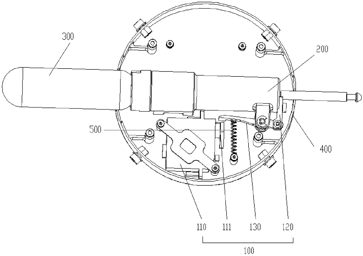
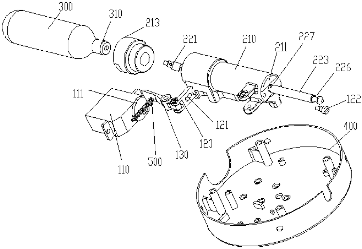
The invention provides a gas release device and an unmanned aerial vehicle and relates to the field of landing equipment for aerial vehicles. A gas release mechanism comprises a trigger mechanism, a striker release mechanism and a gas storage cylinder; the striker release mechanism includes a mounting tube that is hollow, a striker component positioned in the mounting tube and a trigger; one end of the mounting tube is provided with a limiter; the trigger is limited between the limiter and the strike end of the striker component; the opening end of the gas storage cylinder is connected to theend, far away from the limiter, of the mounting tube; the opening end right faces the strike end of the striker component; the trigger mechanism is positioned on one side of the striker release mechanism; when the trigger is in non-operating state, the clamp end, far away from the strike end, of the striker component is extended out of the mounting tube and in clamped connection with the trigger mechanism; when the trigger is in operating state, the striker component strikes the opening end, and the clamp end leaves the trigger mechanism. The gas release device herein enables the parachute ejection distance to be enlarged and assembly difficulty to be relieved, and the influence of spring deformation in the prior art upon parachute ejection is avoided.

Description

technical field [0001] The invention relates to the field of landing equipment for aircraft, in particular to a gas releasing device and an unmanned aerial vehicle. Background technique [0002] With the continuous development of science and technology, the application of drones is becoming more and more extensive, especially when used in the sky above the city, it may be caused by the outside world or the drone itself, causing the drone to fall out of control, causing pedestrians on the ground and The safety of other facilities will affect the safety of the drone and cause the drone to be broken. Therefore, in some drone designs, a parachute device is added to prevent the drone from falling. The most commonly used method at present is to use a spring to eject the parachute, use a parachute or other mechanism to compress the spring, and release the compressed spring to eject the parachute. The method of spring triggering the parachute has relatively high requirements on the...

Claims


Application Information

Patent Timeline
IPC IPC(8): B64D17/72B64D17/80
CPCB64D17/72B64D17/80
Inventor 刘新阳刘玉伟杨礼政
Owner 北京科新信息技术有限公司
Learn More