Ship pod type propeller
A pod-type propeller technology, which is applied in the direction of ship propulsion, propulsion components, outboard propulsion devices, etc., can solve the problems of motor power cannot be increased, power limitation, and small installation space, so as to reduce production difficulty and increase output The effect of high power and transmission efficiency
- Summary
- Abstract
- Description
- Claims
- Application Information
AI Technical Summary
Problems solved by technology
Method used
Image
Examples
Embodiment 1
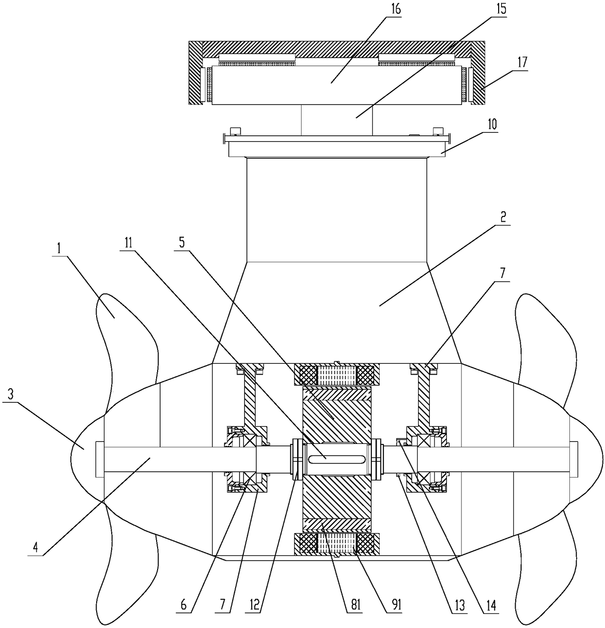
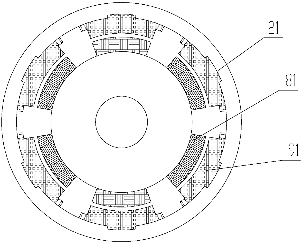
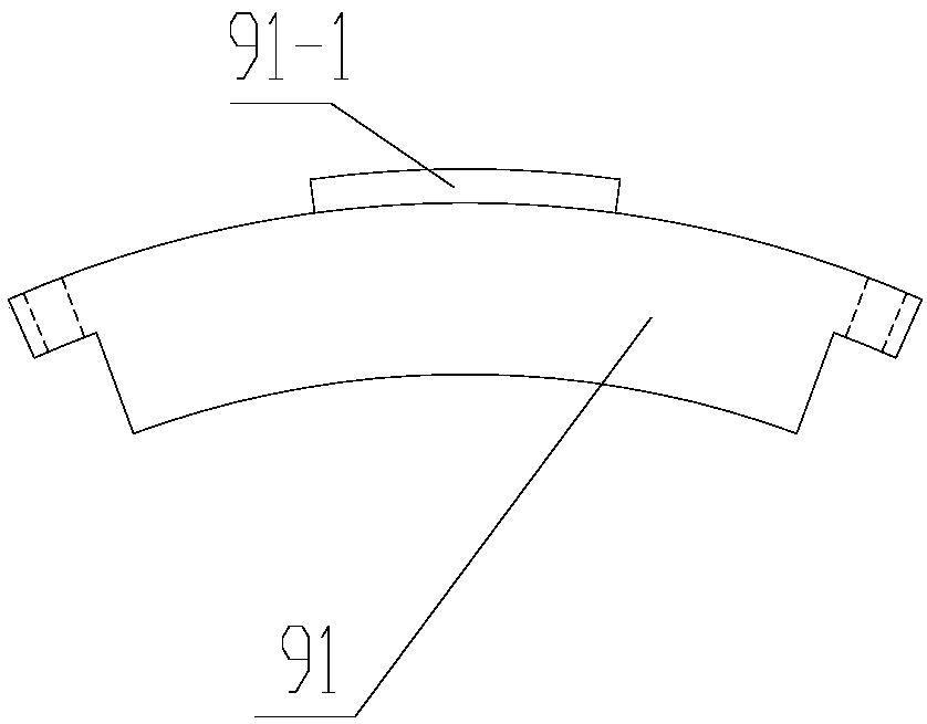
[0031] Such as Figure 1-4 As shown, a ship pod propeller includes a pod housing 2, a propeller 1 and a paddle shaft 4, the pod housing 2 is installed on the hull through a slewing bearing 10, and the paddle shaft 4 is set by The bearing 6 in the pod housing 2 is fixedly installed on the inner cavity bearing seat 7 of the pod housing 2, and the propeller 1 placed outside the pod housing 2 is installed on the propeller shaft 4 ends, the paddle shaft 4 is driven by a permanent magnet synchronous motor; the permanent magnet synchronous motor includes a rotor base 5, a rotor assembly 8 and a stator assembly 9, and the rotor base 5 is fixedly mounted on the paddle shaft 4, the rotor assembly 8 with permanent magnet properties is evenly distributed on the rotor base 5 centered on the axis line of the paddle shaft 4; the stator assembly 9 is fixedly installed on the pod housing 2, Used to provide a rotating magnetic field for the rotor assembly 8; the stator assembly 9 is composed o...
Embodiment 2
[0034] Such as Figure 5-8 As shown, a ship pod propeller includes a pod housing 2, a propeller 1 and a paddle shaft 4, the pod housing 2 is installed on the hull through a slewing bearing 10, and the paddle shaft 4 is set by The bearing 6 in the pod housing 2 is fixedly installed on the inner cavity bearing seat 7 of the pod housing 2, and the propeller 1 placed outside the pod housing 2 is installed on the propeller shaft 4 ends, the paddle shaft 4 is driven by a permanent magnet synchronous motor; the permanent magnet synchronous motor includes a rotor base 5, a rotor assembly 8 and a stator assembly 9, and the rotor base 5 is fixedly mounted on the paddle shaft 4, the rotor assembly 8 with permanent magnet properties is evenly distributed on the rotor base 5 centered on the axis line of the paddle shaft 4; the stator assembly 9 is fixedly installed on the pod housing 2, Used to provide a rotating magnetic field for the rotor assembly 8; the stator assembly 9 is composed o...
Embodiment 3
[0037] Such as Figure 9-10 As shown, a ship pod propeller includes a pod housing 2, a propeller 1 and a paddle shaft 4, the pod housing 2 is installed on the hull through a slewing bearing 10, and the paddle shaft 4 is set by The bearing 6 in the pod housing 2 is fixedly installed on the inner cavity bearing seat 7 of the pod housing 2, and the propeller 1 placed outside the pod housing 2 is installed on the propeller shaft 4 ends, the paddle shaft 4 is driven by a permanent magnet synchronous motor; the permanent magnet synchronous motor includes a rotor base 5, a rotor assembly 8 and a stator assembly 9, and the rotor base 5 is fixedly mounted on the paddle shaft 4, the rotor assembly 8 with permanent magnet properties is evenly distributed on the rotor base 5 centered on the axis line of the paddle shaft 4; the stator assembly 9 is fixedly installed on the pod housing 2, Used to provide a rotating magnetic field for the rotor assembly 8; the stator assembly 9 is composed ...
PUM
 Abstract
Description
Claims
Application Information
 - R&D
- Intellectual Property
- Life Sciences
- Materials
- Tech Scout
- Unparalleled Data Quality
- Higher Quality Content
- 60% Fewer Hallucinations
Browse by: Latest US Patents, China's latest patents, Technical Efficacy Thesaurus, Application Domain, Technology Topic, Popular Technical Reports.
© 2025 PatSnap. All rights reserved.Legal|Privacy policy|Modern Slavery Act Transparency Statement|Sitemap|About US| Contact US: help@patsnap.com


