
Novel PU side module structure

A modular structure, a new type of technology, applied in the direction of building components, building structures, buildings, etc., can solve the problems of composite panel tilting, etc., and achieve the effects of reduced processing costs, convenient replacement of modules, and reasonable position and structure

Pending Publication Date: 2019-03-08
SHANGHAI ZHONGJI MACHINERY
View PDF0 Cites 0 Cited by
  • Summary
  • Abstract
  • Description
  • Claims
  • Application Information

AI Technical Summary

Problems solved by technology

[0006] The technical problem to be solved by the present invention is to provide a new type of PU side module structure, which solves the problem of inclination of the composite board caused by the inconsistency of the stress point of the traditional PU side forming module with different thicknesses. This solution makes the side module delivery system more efficient. Reasonable, the cost of module production is reduced

Method used


Image

  • Novel PU side module structure
  • Novel PU side module structure
  • Novel PU side module structure

Examples


specific Embodiment 1

[0029] A new type of PU side module structure, the chain 5 is provided with a fixing block 9 for supporting the forming module 1, and the fixing block 9 is stuck between the chain pieces of the chain 5 and fixed on the chain 5; the forming module 1 and the fixing block There is a movable connecting piece between 9, and the molding module 1 is fixed on the fixed block 9 by this moving connecting piece.

[0030] The movable connector is a groove and a T-shaped positioning end that cooperate with each other; a groove is provided on the forming module, and fixed iron sheets 7 are arranged on both sides of the opening of the groove; a T-shaped positioning end is provided on the fixed block, and the T-shaped positioning end snaps into the In the groove, the position is limited by fixing the iron sheet.

specific Embodiment 2

[0031] Specific embodiment two, such as image 3 , Figure 4 Shown:

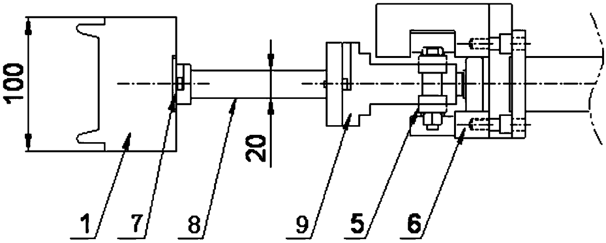
[0032] A new type of PU side module structure, the chain 5 is provided with a fixing block 9 for supporting the forming module 1, and the fixing block 9 is clamped between the chain pieces of the chain 5 and fixed on the chain 5; between the forming module and the fixing block There is a module support arm 8 between them, and the module support arm 8 is movably connected with the forming module 1 and the fixed block 9 .

[0033] The active link structure is as Figure 5 , Figure 6 As shown, it is a groove and a T-shaped positioning structure 11 that cooperate with each other; grooves are provided on the molding module, and fixed iron sheets 7 are arranged on both sides of the groove opening, and the fixed iron sheets 7 are fixed on the molding module 1 by fixing screws 10, forming The module 1 and the fixed iron sheet 7 form a positioning slot, which can directly clamp the forming module 1 on the module...


PUM

PropertyMeasurementUnit
widthaaaaaaaaaa

Abstract

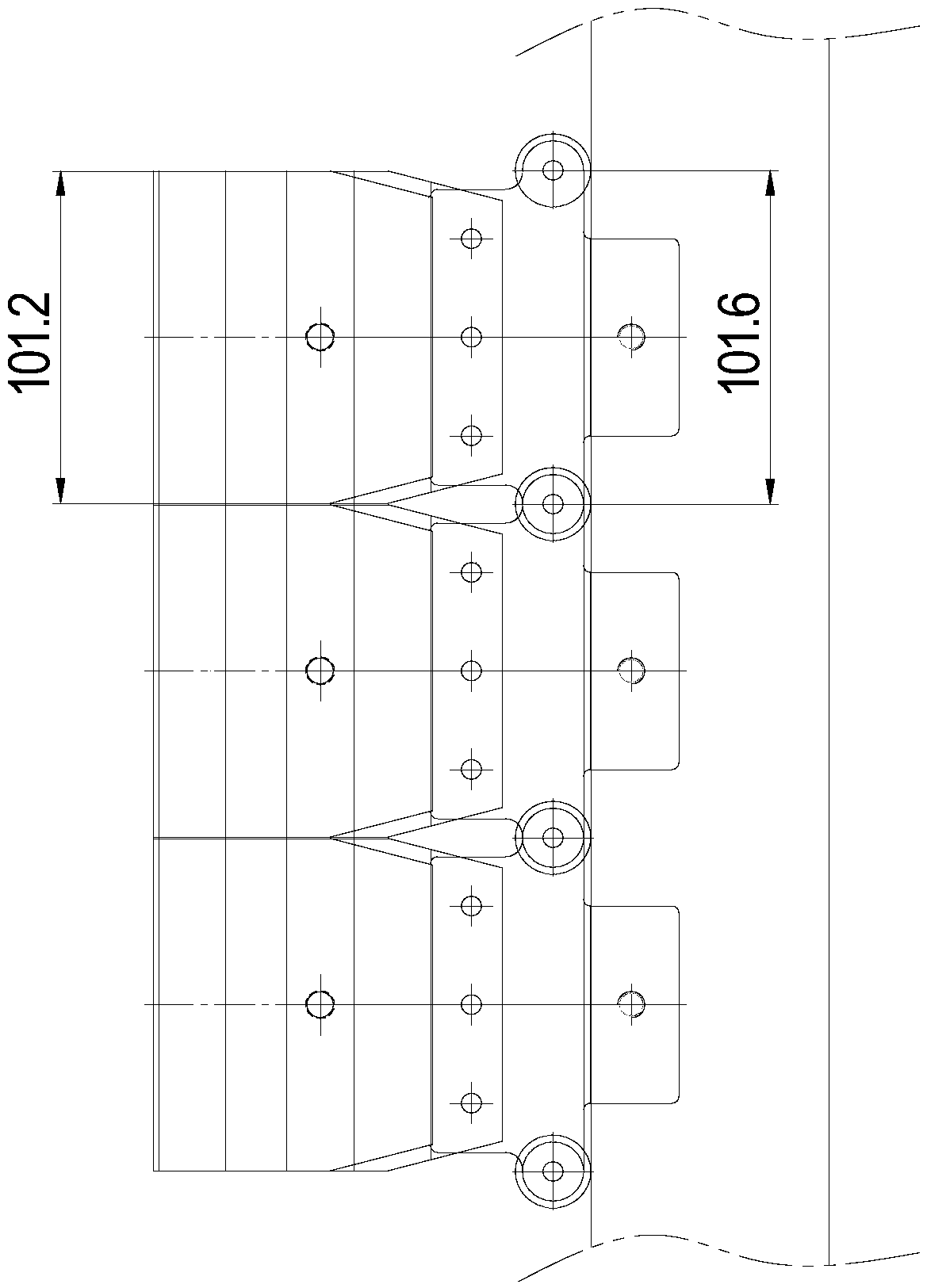
The invention discloses a novel PU side module structure. Fixing blocks used for supporting forming modules are arranged on a chain, and the fixing blocks are clamped between chain pieces of the chainand are fixed on the chain; movable connecting parts are arranged between the forming modules and the fixing blocks, and the forming modules are fixed on the fixing blocks through the movable connecting parts. The long-pitch chain is adopted by a novel PU side module structure, the chain pitch is 200 mm, and the width of each forming module is 199 mm; and the number of the forming modules required by a side module conveying system with the same length is only one half, and the relative machining cost is reduced. When the forming modules with different thicknesses are replaced every time, former modules are lifted upwards and separate from module supporting arms, the novel forming modules are used, the modules are convenient and rapid to replace, and the manufacturing cost is reduced.

Description

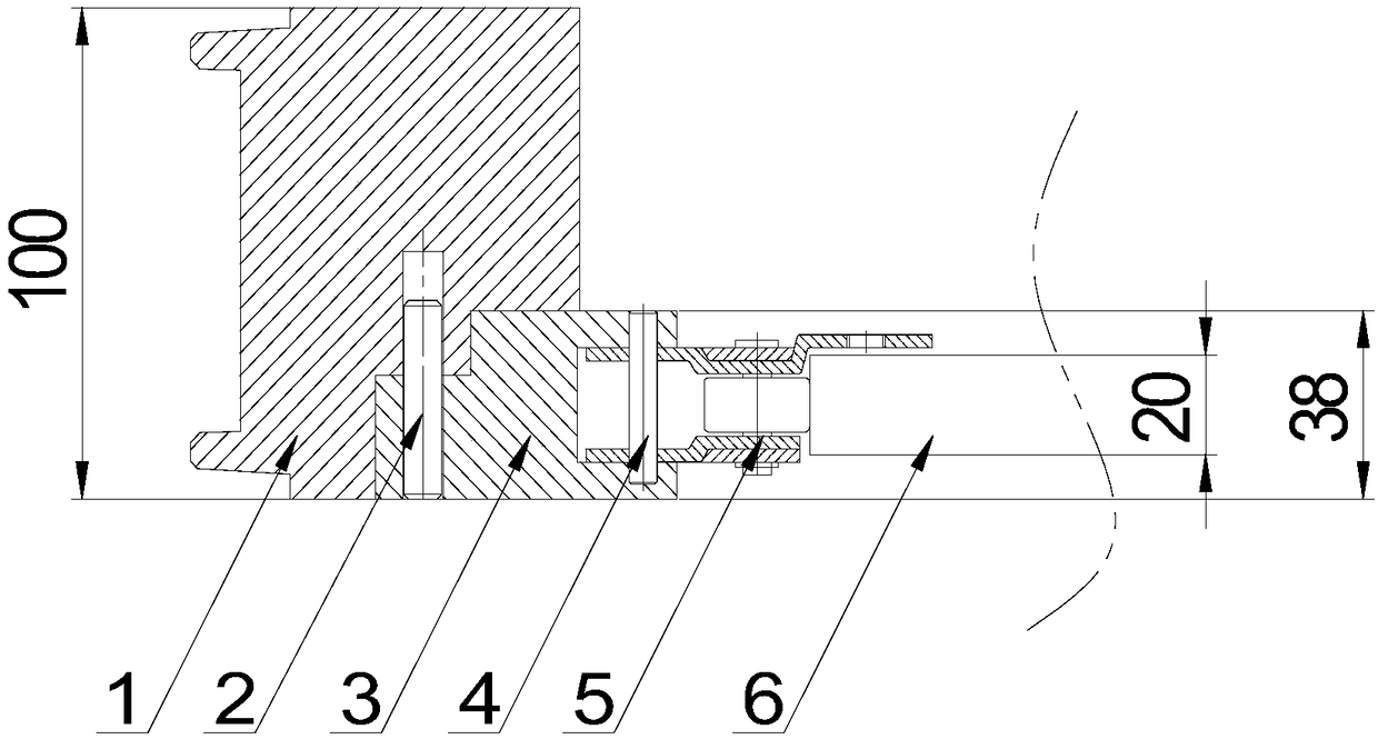
technical field [0001] The invention belongs to the field of rock wool color steel plate production equipment, and in particular relates to a novel PU side module structure. Background technique [0002] The existing PU side module conveying system fixes the forming module on the short-pitch chain through chain transmission, forming a ring shape on the side of the PU main machine. Such as figure 1 , figure 2 shown by molding module 1, pin 2, base block 3, Pin 4, chain 5, guide rail 6 forms. Between the forming module and the base block is a The pin is fixed, and the base block and the chain are passed through The pins are fixed, and the chain runs along the guide rail. [0003] The existing modules have the following deficiencies: [0004] 1. Between the molding module and the basic block is a The pins are fixed. When it is necessary to replace molding modules of different thicknesses, it is troublesome to plug and unplug. This kind of side module structure ...

Claims


Application Information

Patent Timeline
Patent Type & Authority Applications(China)
IPC IPC(8): B29C33/30B29C33/00E04C2/292B29K75/00
CPCB29C33/306B29C33/00B29K2075/00E04C2/292
Inventor 侯树旗李永晖
Owner SHANGHAI ZHONGJI MACHINERY
Learn More