Automatic assembly machine and assembly method for steering knuckle of automobile
A technology for automobile wheel hub and steering knuckle, which is applied in the field of automatic assembly machine and assembly of automobile wheel hub steering knuckle, can solve the problems of unsuitable large-scale industrial automation production, low integration and low work efficiency, and can meet the needs of automated production lines and integrate The effect of high strength and improved support performance
- Summary
- Abstract
- Description
- Claims
- Application Information
AI Technical Summary
Problems solved by technology
Method used
Image
Examples
Embodiment 1
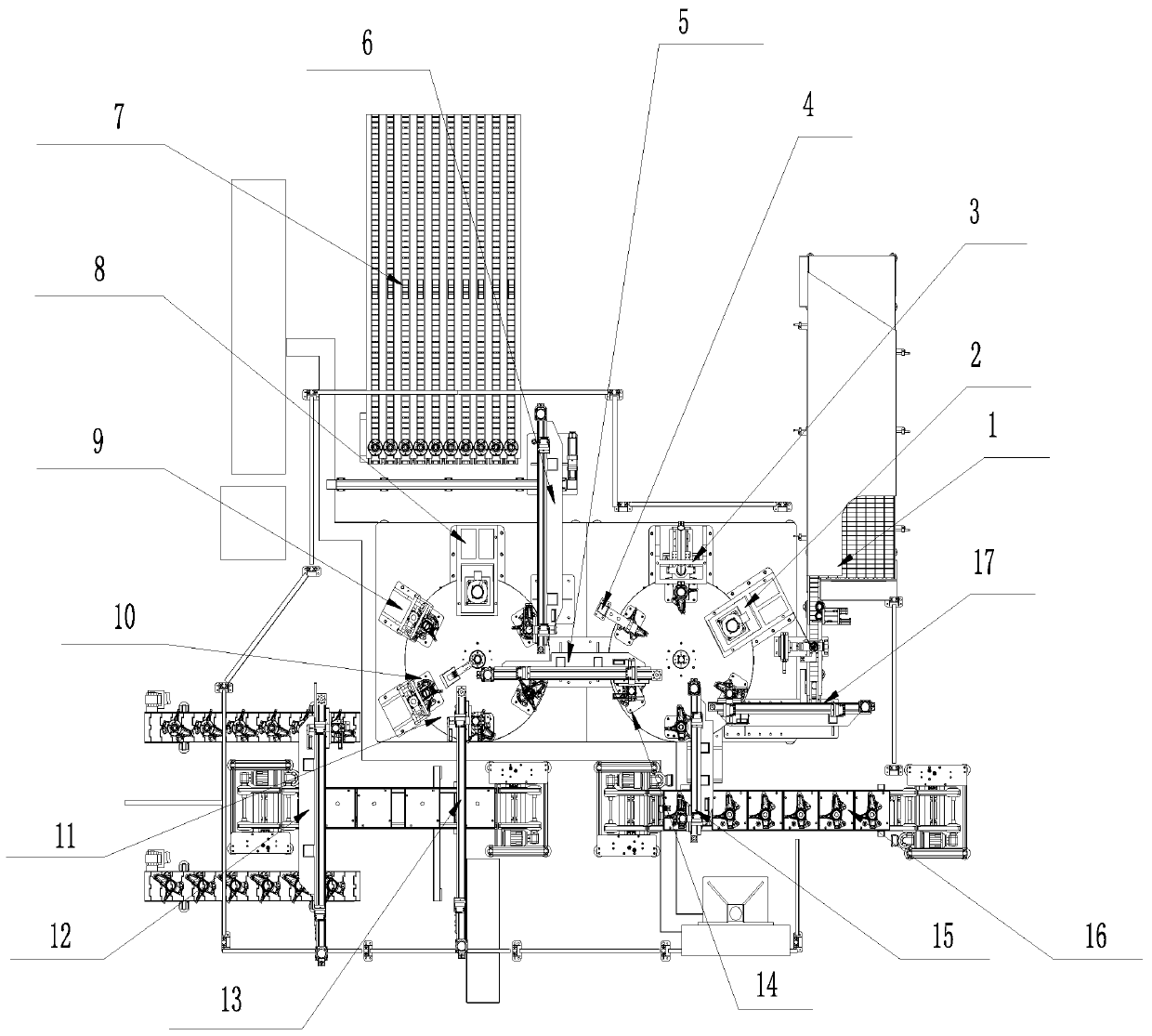
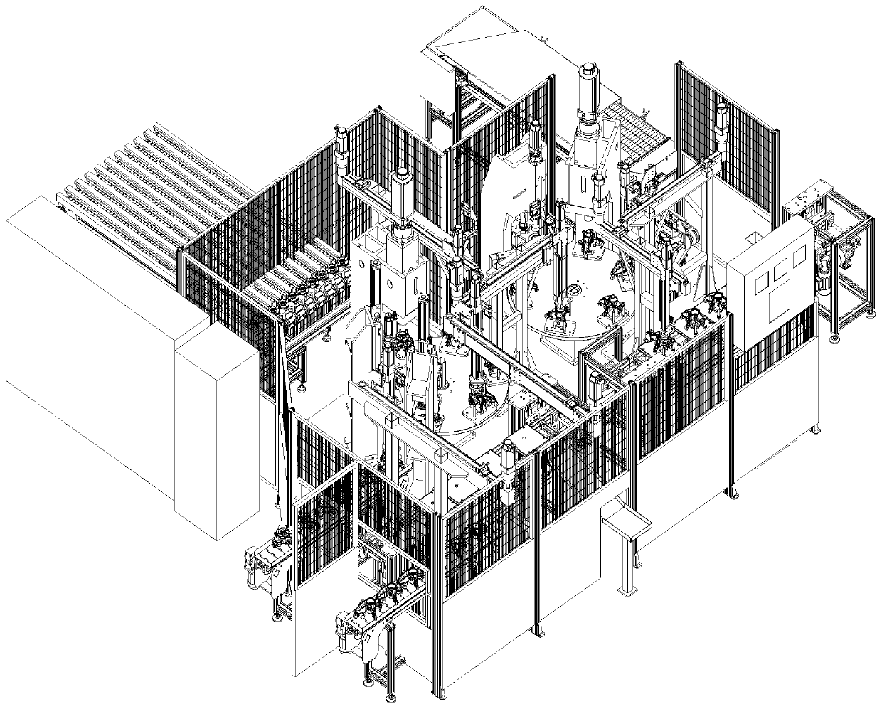
[0041] see Figure 1-11 , a kind of automobile wheel steering knuckle automatic assembly machine, comprises steering knuckle feeding conveyor line 16, and steering knuckle feeding conveyor line 16 is connected with press-fitting device 1 by steering knuckle feeding manipulator 15, and press-fitting device 1 passes bearing feeding manipulator 17 is connected to the bearing bin 1 with a conveying mechanism. The press-fitting device I completes the press-fitting and testing of the steering knuckle, bearings and circlips. The hub feeding manipulator 6 is connected to the hub material bin 7 with a conveying and stopping mechanism, and the pressing device II completes the pressing of the hub, the detection of the runout of the hub end face of the steering knuckle assembly, and the marking of the steering knuckle assembly. II is connected with finished product packaging device 12 by off-line manipulator 13.
Embodiment 2
[0043] On the basis of embodiment 1, also include:
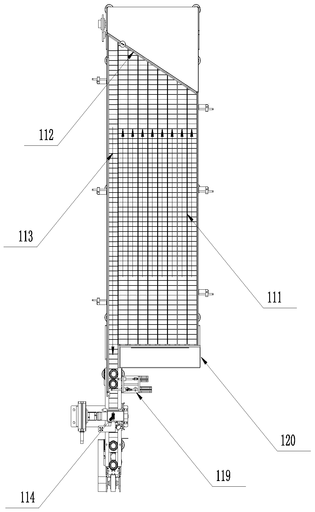
[0044] The bearing silo 1 with a conveying mechanism includes a frame I120, 8 feed conveyor lines I111 are arranged in the length direction of the frame I120, and 1 discharge conveyor line I113 is arranged side by side with the feed conveyor line I111. There is an inclined baffle 112 at the end of I111 and the front end of the discharge conveyor line I113. The baffle 112 forms an acute angle relationship with the discharge conveyor line I113. When the bearings are transported from the feed conveyor line I111 to the baffle 112, they can be removed one by one. Squeeze and push onto the discharge conveyor line I113, and the running speed of the feed conveyor line I111 is greater than that of the discharge conveyor line I113, so as to ensure timely material transportation.
[0045] The outlet end of the discharge conveying line I113 is provided with a stop mechanism I119, and the stop mechanism I119 includes a stop cylinder I, w...
Embodiment 3
[0049] On the basis of embodiment 1, also include:
[0050] Press-fitting device 1 comprises rotary table I14, and described rotary table I14 is provided with bearing press-packing machine 2, circlip feeding press-packing machine 3 and circlip detection machine 4 respectively (rotary table 114, bearing press-packing machine 2, circlip upper The material pressing machine 3 and the snap ring detection machine 4 all adopt the molding equipment of the prior art, and will not be described here). The lower part of the rotary table 1 is facing the bearing press machine 2 and the spring feeding press machine 3. There is a slope self-locking support mechanism (due to the angle of view in the figure 1 not shown in ).
[0051] The press-fitting device II includes a rotary table II11, and the rotary table II11 is respectively equipped with a hub press-fitting machine 8, a steering knuckle assembly hub end face runout detection machine 9 and a steering knuckle assembly marking machine 10 ...
PUM
 Abstract
Description
Claims
Application Information
 - R&D
- Intellectual Property
- Life Sciences
- Materials
- Tech Scout
- Unparalleled Data Quality
- Higher Quality Content
- 60% Fewer Hallucinations
Browse by: Latest US Patents, China's latest patents, Technical Efficacy Thesaurus, Application Domain, Technology Topic, Popular Technical Reports.
© 2025 PatSnap. All rights reserved.Legal|Privacy policy|Modern Slavery Act Transparency Statement|Sitemap|About US| Contact US: help@patsnap.com


