
Stamping device for casting machining

A punching device and casting technology, applied in the field of punching equipment, can solve problems such as low efficiency and manual feeding, and achieve the effects of reducing risk, convenient operation and improving work efficiency

Pending Publication Date: 2019-03-08
阜宁隆德机械制造有限责任公司
View PDF4 Cites 2 Cited by
  • Summary
  • Abstract
  • Description
  • Claims
  • Application Information

AI Technical Summary

Problems solved by technology

[0003] A stamping device for casting processing proposed by the present invention solves the problems of manual loading and low efficiency of existing stamping devices

Method used


Image

  • Stamping device for casting machining
  • Stamping device for casting machining
  • Stamping device for casting machining

Examples


Embodiment Construction

[0019] The following will clearly and completely describe the technical solutions in the embodiments of the present invention with reference to the accompanying drawings in the embodiments of the present invention. Obviously, the described embodiments are only some, not all, embodiments of the present invention.

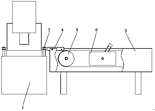
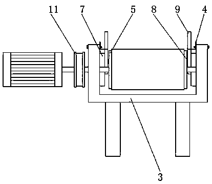
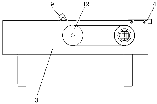
[0020] refer to Figure 1-5 , a stamping device for casting processing, comprising a stamping equipment main body 1, a guide wheel 2 is fixedly installed on the top wall of the base of the stamping equipment main body 1, a conveying device is arranged on the left side of the stamping equipment main body 1, and the conveying device includes a housing 3, and the housing 3 An angle iron 4 is fixedly installed on the top left side of the front and rear inner side walls of the housing 3, and two symmetrically distributed rollers 5 are arranged on the left and right sides of the inside of the housing 3, and a booster device 6 is arranged between the two rollers 5. The push...


PUM


Abstract

The invention discloses a stamping device for casting machining. The following scheme is provided aiming at the problems that manual feeding is needed for existing stamping equipment, the efficiency is low, and a certain risk exists. The scheme of the stamping device comprises a stamping equipment main body, wherein guide wheels are installed on the top wall of the base of the stamping equipment main body, and the left side of the stamping equipment main body is provided with a conveying device; the conveying device comprises a shell, angle irons are arranged on the left side of the top of thefront inner side wall and the left side of the top of the rear inner side wall of the shell respectively, two symmetrically distributed rollers are arranged on the left side and the right side of theshell body, and a boosting device is arranged between the two rollers; the boosting device comprises a groove body, a groove is formed in the inner wall of the groove body, a short shaft is arrangedin the groove in a sliding mode, and the other end of the short shaft is provided with a rotating rod in a sleeve mode; and a motor is arranged outside the back side of the shell, an output shaft of the motor is connected to a driving wheel, and the driving wheel is connected to a driven wheel through a belt. According to the stamping device, the labor intensity is reduced, the danger is reduced,and the working efficiency is improved.

Description

technical field [0001] The invention relates to the field of stamping equipment, in particular to a stamping device for casting processing. Background technique [0002] The existing stamping equipment for casting processing is usually manually loaded, which is laborious and laborious, and the safety cannot be guaranteed. In the actual production process, machine failures, mold damage, etc. may cause accidents. Therefore, We have designed a stamping device for casting processing to solve the above problems. Contents of the invention [0003] The invention proposes a stamping device for casting processing, which solves the problems of manual feeding and low efficiency of the existing stamping device. [0004] In order to achieve the above object, the present invention adopts the following technical solutions: [0005] A stamping device for casting processing, comprising a stamping equipment main body, a guide wheel is fixedly installed on the top wall of the base of the s...

Claims


Application Information

Patent Timeline
Patent Type & Authority Applications(China)
IPC IPC(8): B21D43/02
CPCB21D43/02
Inventor 王昌来
Owner 阜宁隆德机械制造有限责任公司
Learn More