Vascular stent prosthesis for preventing peripheral leakage from creased skirt edge, processing method and skirt edge creasing method
A vascular stent and processing method technology, which is applied to prostheses, catheters, balloon catheters, etc., can solve the problems of increasing the complexity and difficulty of control, the overall product is too long, and the effect is not ideal, and achieves safe and convenient use. Circulation leakage phenomenon, the effect of preventing loosening
- Summary
- Abstract
- Description
- Claims
- Application Information
AI Technical Summary
Problems solved by technology
Method used
Image
Examples
Embodiment 1
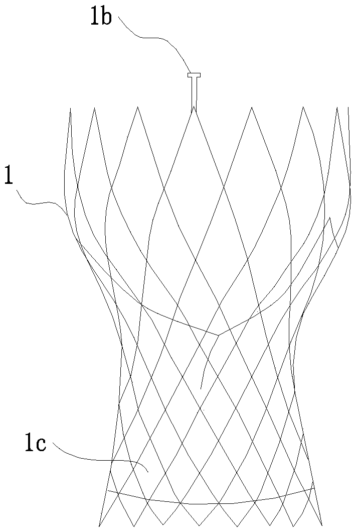
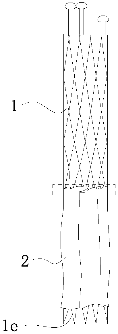
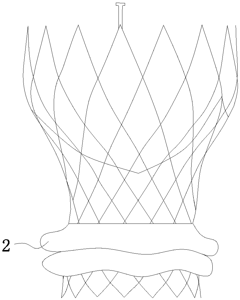
[0369] see Figure 1b , Figure 1c , the vascular stent prosthesis of the present embodiment includes a stent 1, the periphery of the stent 1 is provided with a flexible skirt 2, and the traction cable (omitted in the figure, the specific threading mode of the traction cable can be combined with other implementations) is threaded on the skirt 2. For example), the traction wire is linked with the radial deformation when the stent is released to drive the skirt into a stacked state. Before the stent 1 is released, that is, the stent is in a radially compressed state. Before the intervention, the stent is loaded into the delivery system and placed in the sheath Under the shackles of the skirt, it is generally in a so-called compressed state. At this time, the circumference of the skirt is discounted in a roundabout way ( Figure 1b visible within the dotted box).
[0370] The skirt 2 of the stent 1 is in a spread state before it is released. It stretches axially and surrounds t...
Embodiment 2
[0380] see Figure 2a ~ Figure 2d , in this example, see Figure 2a , a flexible skirt 2 is provided on the periphery of the bracket 1, and the top edge of the skirt 2 is fixed on the outer periphery of the bracket 1. After release, skirt 2 is stacked ( Figure 2d ), gather and stack along the axial direction of the released stent 1 and form a ring-shaped peripheral leakage sealing part. A traction cable 4 is threaded on the skirt 2, and the traction cable 4 is linked with the radial deformation of the support 1 when it is released.
[0381] The traction cable 4 includes a driving part 4a and a force applying part 4b, wherein the driving part 4a is movably threaded on the skirt 2 . The force application part 4b is connected to the skirt 2 and moves through the corresponding part of the skirt. The force application part 4b is pulled by the drive part 4a during the release process of the bracket 1 and has an axial displacement relative to the bracket 1 to lift the skirt 2 for...
Embodiment 3
[0392] see Figure 3a and Figure 3b , in this embodiment, the periphery of the bracket 1 is provided with a flexible skirt 2, the skirt 2 is in a spread state before the bracket 1 is released, stretches axially and surrounds the periphery of the bracket 1 before the release, after the bracket 1 is released, the skirt 2 is In the stacked state, the stent 1 is folded and stacked along the axial direction of the released stent 1 to form a ring-shaped peripheral leakage sealing part.
[0393] In this embodiment, the stent 1 adopts a vascular stent prosthesis, which can be used in large blood vessels such as the aorta. The shape and characteristics of the stent in the previous embodiment are different from the location of use, but the skirt setting and working principle are similar.
[0394] In this embodiment, the skirt 2 is made of elastic material, and is tightened around the periphery of the bracket when the bracket is released. In the release process, the skirt and the brac...
PUM
 Abstract
Description
Claims
Application Information
 - R&D
- Intellectual Property
- Life Sciences
- Materials
- Tech Scout
- Unparalleled Data Quality
- Higher Quality Content
- 60% Fewer Hallucinations
Browse by: Latest US Patents, China's latest patents, Technical Efficacy Thesaurus, Application Domain, Technology Topic, Popular Technical Reports.
© 2025 PatSnap. All rights reserved.Legal|Privacy policy|Modern Slavery Act Transparency Statement|Sitemap|About US| Contact US: help@patsnap.com


