Silencer
A muffler and container technology, which is applied to mufflers, machines/engines, engine components, etc., can solve the problems such as the increase of the outer diameter of the muffler main body 11 and the increase of the vehicle width, etc., so as to improve rigidity, reduce exhaust sound, suppress sound effect
- Summary
- Abstract
- Description
- Claims
- Application Information
AI Technical Summary
Problems solved by technology
Method used
Image
Examples
Embodiment 1
[0038] First, Embodiment 1 of the present invention will be described based on the drawings.
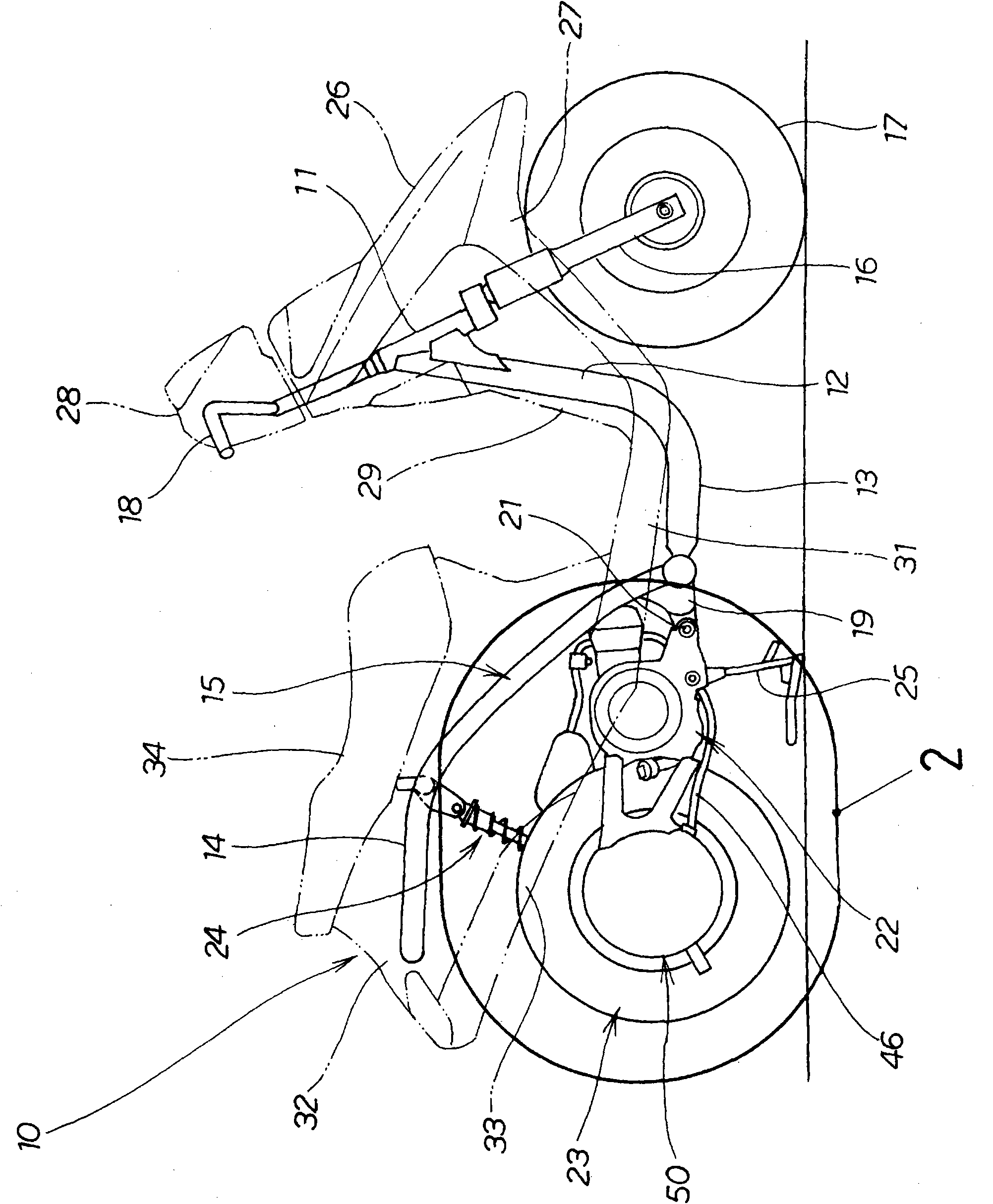
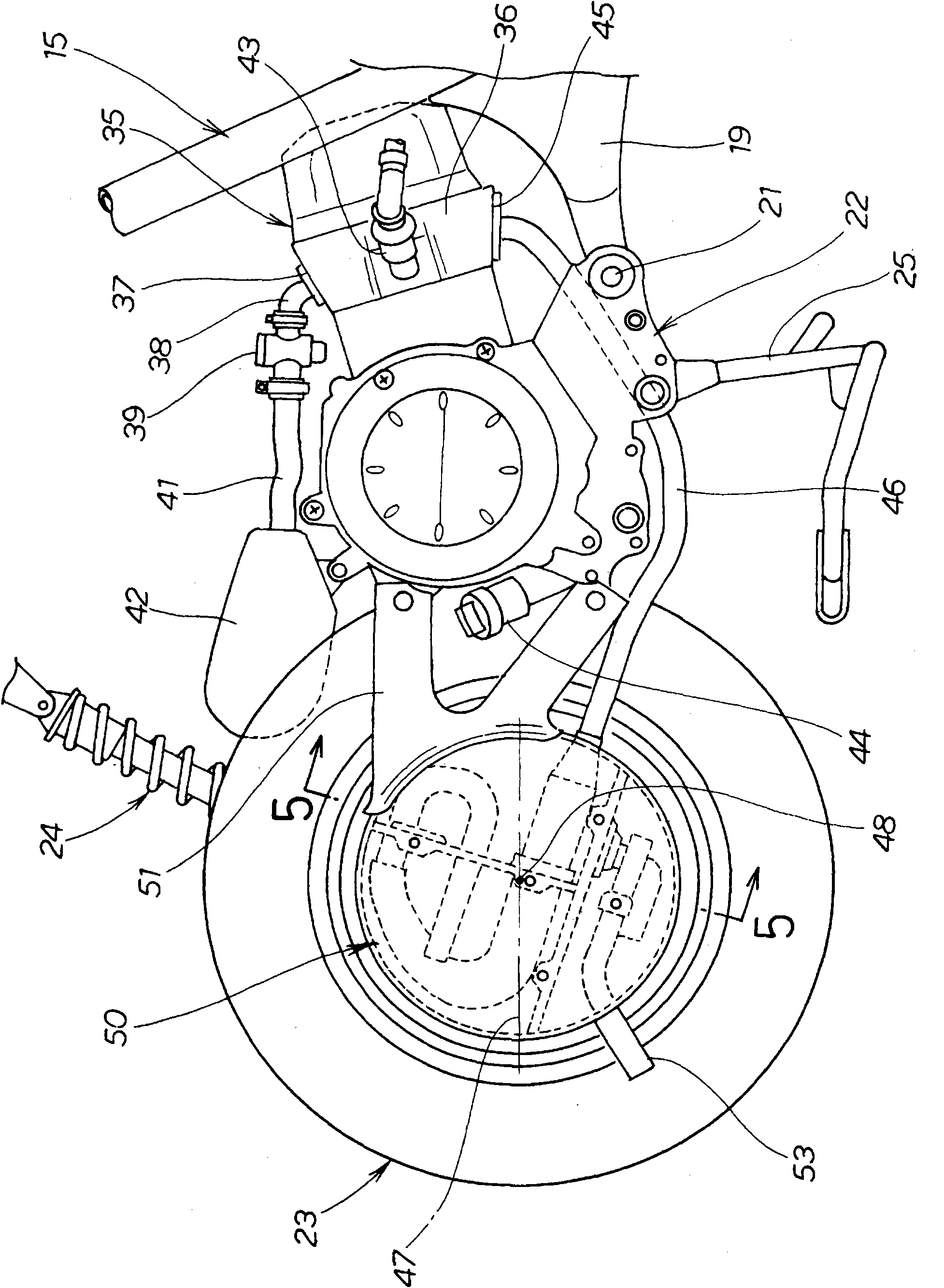
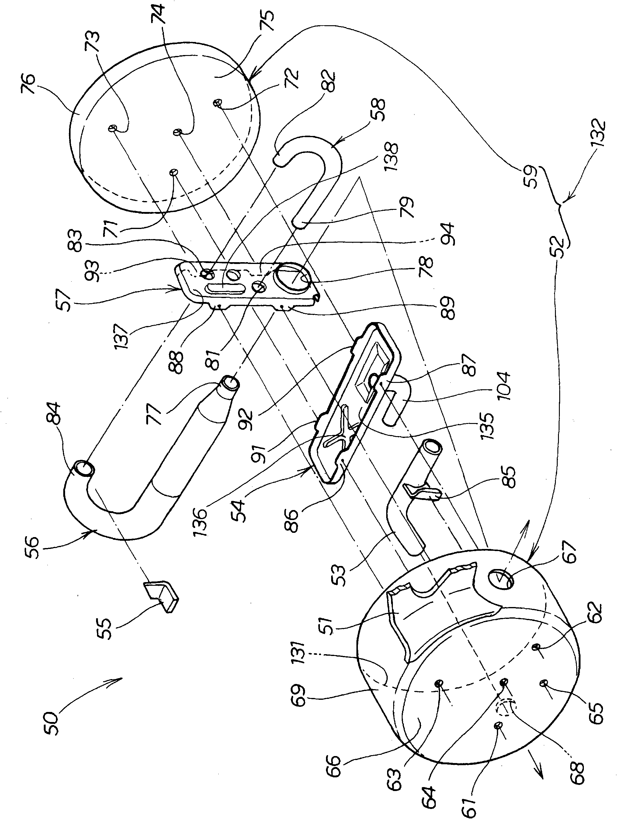
[0039] Such as figure 1 As shown, the two-wheeled motor vehicle 10 is equipped with a vehicle frame 15, and the vehicle frame 15 is composed of the following components: a steering standpipe 11; a down tube (down tube) 12 extending obliquely downward from the steering stand tube 11; 12, a lower tube (lower tube) 13 extending horizontally to the rear at the lower end of the lower tube; And the motorcycle 10 also has: a front fork 16, the front fork 16 is rotatably mounted on the steering standpipe 11; a front wheel 17, the front wheel 17 is rotatably arranged at the lower end of the front fork 16; handle 18, the handle 18 is provided on the upper end of the front fork 16; a unit swing (described in detail later) 22, the unit swing 22 is provided on the connecting member in a vertically rotatable manner via a pivot 21 19, the connecting member 19 further extends rearward from the rea...
Embodiment 2
[0090] Next, Embodiment 2 of the present invention will be described based on the drawings.
[0091] exist Figure 7 in, for with figure 2 The same symbols are used for the same structure and descriptions are omitted. In addition, for the convenience of description, the muffler support brace 51 is shown with a dashed-two dotted line.
[0092] exist Figure 7 In the figure (a), the muffler 50B is equipped with the drum 145 integrally formed with the side wall part 143 which is an ellipse cylindrical shape in side view, and the ellipse-shaped first bottom part 144. Let W1 be the minimum width of the side wall portion 143 when viewing the drum 145 (viewing from a direction perpendicular to the first bottom portion 144 ).
[0093] Figure 7 Figure (b) is along the Figure 7 In the cross-sectional view of line b-b in (a), the interval between the first bottom 144 and the elliptical second bottom 147 combined by the first partition 145 and the second partition 146 is H1. In ...
PUM
 Abstract
Description
Claims
Application Information
 - Generate Ideas
- Intellectual Property
- Life Sciences
- Materials
- Tech Scout
- Unparalleled Data Quality
- Higher Quality Content
- 60% Fewer Hallucinations
Browse by: Latest US Patents, China's latest patents, Technical Efficacy Thesaurus, Application Domain, Technology Topic, Popular Technical Reports.
© 2025 PatSnap. All rights reserved.Legal|Privacy policy|Modern Slavery Act Transparency Statement|Sitemap|About US| Contact US: help@patsnap.com


