
A CD-ROM staggered optical storage system

A staggered arrangement and optical storage technology, applied in information storage, recording information storage, modifying equipment to store record carriers, etc., can solve problems such as the difficulty of multi-manipulator cooperation, insufficient disc access efficiency, and unreasonable layout design. , to achieve the effect of improving the efficiency of CD-ROM access and reading and writing, speeding up the speed and accuracy, and improving the precision

Active Publication Date: 2019-03-05
BEIJING ZHONGKE KAIDI SOFTWARE CO LTD
View PDF10 Cites 10 Cited by
  • Summary
  • Abstract
  • Description
  • Claims
  • Application Information

AI Technical Summary

Problems solved by technology

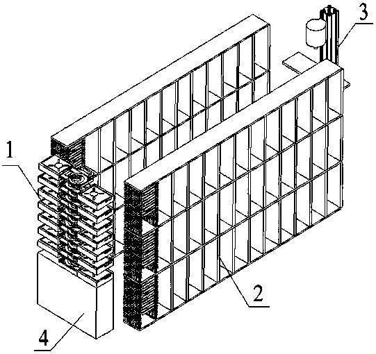
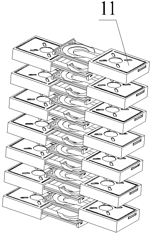
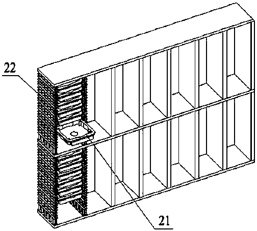
[0006] In order to overcome the existing problems in existing optical storage devices, such as unreasonable layout design, insufficient optical disc access efficiency, and difficulty in multi-manipulator cooperation, the present invention provides an optical storage system with interleaved optical drives. It is installed at one end of the storage system in a staggered arrangement. The disc storage rack is used to place the disc case. Each disc case stores a stack of discs. The disc manipulator assembly moves along the channel between the disc storage racks. The disc manipulator assembly can be accessed in a push-pull manner. The CD box can also access the CDs in the CD box. Based on the design of the staggered arrangement of the CD-ROM drives, when the CD-ROM manipulator assembly puts the CD-ROM into the CD-ROM drive, it only needs to move vertically to put the CDs into the CD-ROM drive one by one, reducing It reduces the error and time consumed caused by multiple horizontal movements, thereby improving the access efficiency of the disc, increasing the stability of the entire system, and also improving the data reading and writing speed of the system.

Method used


Image

  • A CD-ROM staggered optical storage system
  • A CD-ROM staggered optical storage system
  • A CD-ROM staggered optical storage system

Examples


Embodiment Construction

[0017] The present invention will be further described below in conjunction with the accompanying drawings and embodiments, and the described embodiments are only some embodiments of the present invention, not all embodiments. Based on the embodiments of the present invention, all other embodiments obtained by persons of ordinary skill in the art without creative efforts fall within the protection scope of the present invention.

[0018] The structures, proportions, sizes, quantities, etc. shown in the drawings attached to this specification are only used to match the content disclosed in the specification, for those who are familiar with this technology to understand and read, and are not used to limit the implementation of the present invention. Limiting conditions, so there is no technical substantive meaning, any modification of structure, change of proportional relationship or adjustment of size, without affecting the effect and purpose of the present invention, should sti...


PUM


Abstract

A CD-ROM staggered optical storage system includes CD-ROM drive walls, a CD storage rack, a CD-ROM manipulator assembly, a distribution box, etc. The CD-ROM drive walls are composed of two rows of CD-ROM drive arranged in opposite staggered arrangement, the CD storage rack is used for storing that CD case, a stack of optical disc is stored in each optical disc case. The CD-ROM manipulator assemblyincludes a CD-ROM cassette push-pull manipulator, a CD access manipulator and a guide rail support, and the whole system running process comprises the optical disc manipulator assembly is moved alonga track in a channel between two rows of optical disc storage frames to a designated optical disc cartridge position, the push-pull manipulator of the optical disc case pulls out the optical disc case, the optical disc access manipulator takes out the optical disc and puts it into the optical disc drive in turn, after reading and writing, the optical disc access manipulator takes out the opticaldisc and puts it back into the optical disc case, and the push-pull manipulator pushes the optical disc case back to the original position.

Description

technical field [0001] The invention relates to the field of large-capacity optical storage devices, in particular to an optical storage system with interleaved optical drives. Background technique [0002] Optical storage is a mass data storage technology that uses optical discs as storage media. It has the advantages of low energy consumption, strong environmental adaptability, and long data storage period. It is very suitable for storing data with low access frequency and long storage time. [0003] Among the existing storage methods, magnetic storage and electric storage are widely used. Magnetic storage is mainly disk and magnetic tape storage, and electric storage is mainly hard disk storage. At present, most data centers around the world use magnetic storage. Magnetic storage has inherent weaknesses, such as strict requirements on the storage environment, susceptibility to external electromagnetic interference, easy data loss, and high maintenance costs. Optical stor...

Claims


Application Information

Patent Timeline
Patent Type & Authority Applications(China)
IPC IPC(8): G11B17/22G11B33/04
CPCG11B17/221G11B33/0438Y02D10/00
Inventor 张理宁萌白世杰张艺超
Owner BEIJING ZHONGKE KAIDI SOFTWARE CO LTD
Learn More