Friable rock stratum sample-collection drill pipe structure

A sample collection and drill pipe technology, which is applied in the field of geological exploration, can solve problems such as low core recovery rate, influence on accuracy, and inability to analyze and detect, and achieve the effects of improving solidification efficiency, avoiding separation and fragmentation, and improving sampling effect

Active Publication Date: 2019-03-01
胡楠
View PDF9 Cites 2 Cited by
  • Summary
  • Abstract
  • Description
  • Claims
  • Application Information

AI Technical Summary

Problems solved by technology

[0002] At present, in the early stage of civil engineering construction, road and bridge laying, coal mine excavation, oil and gas exploitation, etc., it is necessary to sample and analyze the geomorphic rock-soil structure. When sampling, we often encounter loose soil layers, such as tidal flats or broken rock layers. Therefore, it is necessary to analyze the original structure, permeability and porosity of loose sediments and broken rock formations. Due to the loose and fragile structure of such samples, the quality of obtained samples is poor and cannot be used for analysis and detection. Due to the limitations of power and equipment structure , the existing sampling drill pipes are all hollow structures, and the sleeves are used to rotate samples to collect samples. However, due to the loose structure, they are easy to fall off during sampling, and it is often difficult to obtain high-quality core samples with regular shapes. Not only for loose and fragile rock formations The core recovery rate is low, and the core is often accompanied by secondary damage during the core extraction process. Some existing methods use a combination of cooling fluid to freeze and solidify loose and fragile rock formations, and then re-sampling, resulting in the outer edge of the sample being cut and squeezed. , affect the composition of the sample, and ultimately affect the accuracy of detection
[0003] Publication number CN206583629U discloses a soil sampler and a soil sampling device, including a drill bit, a drill rod and a motor, the drill bit is connected to the drill rod, and the end of the drill rod away from the drill bit is connected to the motor, so The motor is used to drive the drill rod, and the side wall of the drill bit near the preset distance of the drill rod is provided with a second opening with a preset thickness along the circumference of the drill bit as a first layered socket, so A third opening with a preset thickness is provided along the circumference of the drill bit at a preset distance from the first layered socket on the side wall of the drill bit as a second layered socket. Sampling of rock and soil is also not able to form blocky structures

Method used


Image

  • Friable rock stratum sample-collection drill pipe structure
  • Friable rock stratum sample-collection drill pipe structure
  • Friable rock stratum sample-collection drill pipe structure

Examples


Embodiment 1

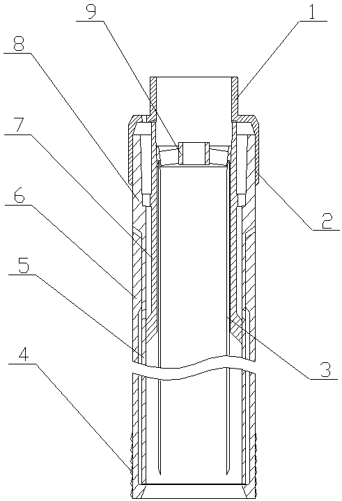
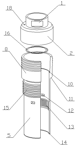
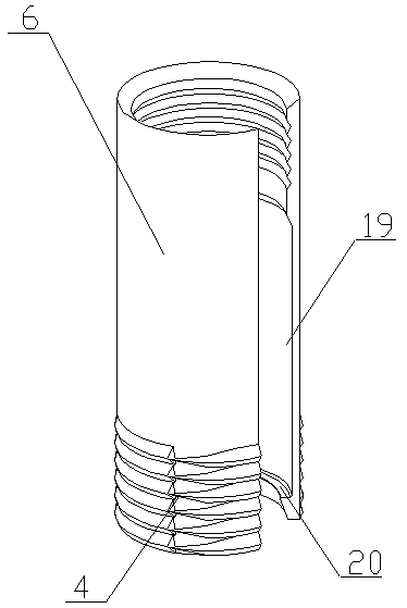
[0020] The structure of the drill pipe for sample collection of fragile rock formations of the present invention is realized in this way, consisting of the drill pipe chuck (1), connecting sleeve (2), sampling pipe (3), drill pipe edge (4), lower partition pipe (5), Outer drill bushing (6), inner bushing (7), upper fixing sleeve (8), sampling chuck (9), inner limiter (10), outer limiter (11), communication groove (12), Internal thread (13), gasket (14), external thread (15), sealing ring (16), tapered communication hole (18), inner annular groove (19), inner supporting ring (20), outer annular groove ( 21), the limit ring (22) and the diversion groove (23), the inner support ring (20) is placed on the inner wall of one end of the outer drill sleeve (6), and the inner diameter of the inner support ring (20) gradually increases from bottom to top reduced, multiple groups of drill pipe edges (4) are equidistantly arranged on the outer wall of the outer drill sleeve (6), and the d...

Embodiment 2

[0023] The difference between this embodiment and Embodiment 1 is that: the outer wall of the inner bushing (7) is provided with a deflector (24), which is located in the lower chamber, and the deflector (24) is a spiral plate. The deflector (24) is provided with a plurality of through holes (17), which are distributed in a spiral. When in use, when the coolant is injected, the coolant flowing into the lower chamber through the guide groove (23) will flow in a spiral along the deflector (24), and then the coolant will be distributed in the lower chamber more uniform;

[0024] The inner diameter of the inner support ring (20) is designed to gradually decrease from bottom to top, so that the inner surface of the inner support ring (20) is inclined, and then the soil sample gradually enters the lower dividing tube (5) along the inclined surface. to sample;

[0025] A sealing gasket (14) is placed on the other end surface of the lower separating pipe (5), and it is designed to fit...


PUM


Abstract

The invention discloses a friable rock stratum sample-collection drill pipe structure, particularly discloses a drill pipe structure; according to the drill pipe structure, multiple layers of structures are combined to form a circular hollow zone, external refrigerants keep the hollow zone at a low temperature, so that the outer sides of samples are solidified to form protective shells, and soil sample in the core portion is separated and collected through a sampling tube. The outer edges of the samples cannot be squeezed due to the fact that cooling is performed after sampling. The drill pipestructure is characterized in that an inner support ring is arranged on the inner wall of one end of an outer drill bushing, the inner diameter of the inner support ring is reduced gradually from bottom to top, multiple groups of drill pipe edges are arranged on the outer wall of the outer drill bushing at equal intervals, drill pipe edges in the same group are arranged circularly, the width of the drill pipe edges is reduced gradually from one end to the other end gradually, an inner circular groove is formed in the inner side wall of the outer drill bushing, one end of the inner circular groove extends to the position of the inner support ring, a lower spacer tube is arranged in the outer drill bushing, one end of the lower spacer tube is screwed with the other end of the outer drill bushing through external threads, and a seal gasket is arranged on the end face of the other end of the lower spacer tube, and fits the inner support ring well.

Description

technical field [0001] The invention relates to a drill pipe structure for collecting samples of fragile rock formations, and relates to a drill pipe for collecting samples of fragile rock and soil through a multi-layer structure in the process of geological exploration, belonging to the field of geological exploration. In particular, it relates to a drill pipe structure that adopts a combination of multi-layer structures to form an annular hollow area, cooperates with an external refrigerant to cool in the hollow area, so that the outer side of the sample solidifies to form a protective shell, and separates and collects the soil sample at the core position through the sampling tube. . Background technique [0002] At present, in the early stage of civil engineering construction, road and bridge laying, coal mine excavation, oil and gas exploitation, etc., it is necessary to sample and analyze the geomorphic rock-soil structure. When sampling, we often encounter loose soil l...

Claims


Application Information

Patent Timeline
Patent Type & Authority Applications(China)
IPC IPC(8): G01N1/08
CPCG01N1/08
Inventor 不公告发明人
Owner 胡楠
Why Eureka
Try Eureka