
Double-air-channel central air-conditioning unit and control method thereof

A central air-conditioning and unit technology, applied in heating and ventilation control systems, control input related to air characteristics, space heating and ventilation control input, etc. Unable to stabilize and other issues

Active Publication Date: 2019-03-01
GUANGDONG CONSTR VOCATIONAL TECH INST
View PDF6 Cites 3 Cited by
  • Summary
  • Abstract
  • Description
  • Claims
  • Application Information

AI Technical Summary

Problems solved by technology

[0002] In some special applications, it is necessary to use fresh air and ultra-low temperature air supply to meet certain process requirements. Such applications require that the temperature of the air supply should be within a certain range below zero regardless of the ambient temperature of the outdoor fresh air. Among them - The air supply requirement of 5°C to 0°C is common, and some places require the air supply requirement of -5°C to -10°C. If the air supply temperature of such a low temperature needs to be met, the conventional primary refrigeration system cannot meet the requirements, and multiple cooling systems are required. The way of cascade refrigeration system realizes the low-temperature refrigeration treatment of the supply air temperature, and the air to be treated usually contains moisture. When the water in the water passes through the evaporator, it will freeze, and the formed ice will increase the resistance of the air passing through the evaporator. When the ice blockage is serious, it will even cause the air volume to fail to pass through all the evaporators and reach the air outlet. In any case, the internal resistance of the air duct will increase sharply. If it is not dealt with in time, it will cause the blower to overload and alarm, and the unit will stop and cannot operate.
[0003] In the existing technology, in the treatment of this type of air conditioner, the ultra-low temperature air supply is realized by adopting a multi-stage refrigeration system in series, but in the treatment of the air path, although a relatively independent dual air path system and a relatively independent refrigeration system are adopted, Realize the one-use and one-standby control of two air channels and two refrigeration system channels to maintain the long-term ultra-low temperature air supply requirements, but in the two air channels one-use and one-standby control processing, the existing technology usually uses a single parameter such as The control logic is too simple in the specific switching control. Usually, when the pressure difference of the unit is higher than a certain pressure difference, it is switched from the current air path to the standby air path, and the cooling path is carried out according to this condition. switch
This switching mode does not fully consider the effect of (1) the higher evaporation temperature of the new air path on the outlet air temperature (the outlet air temperature will rise temporarily) during the switching process of the two air paths, (2) The ice-blocked evaporator in the channel relies on natural heat exchange to defrost slowly (this problem is more prominent when the outdoor ambient temperature is low)
(3) It often happens that the evaporator in the switched air duct is not fully defrosted and will be switched to the operating air duct, resulting in the switching between the air ducts becoming more and more frequent with the extension of the operating time of the unit
The disadvantages are finally manifested as: (1) The temperature of the outlet air cannot be stabilized
(2) Frequent switching between air ducts leads to serious damage to the life of each electric valve and reduces the reliability of the unit

Method used


Image

  • Double-air-channel central air-conditioning unit and control method thereof
  • Double-air-channel central air-conditioning unit and control method thereof
  • Double-air-channel central air-conditioning unit and control method thereof

Examples


Embodiment Construction

[0046] The present invention provides a dual-airway central air-conditioning unit and its control method. In order to make the purpose, technical solution and effect of the present invention clearer and clearer, the present invention will be further described in detail below with reference to the accompanying drawings and examples. It should be understood that the specific embodiments described here are only used to explain the present invention, not to limit the present invention.

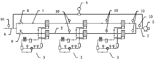
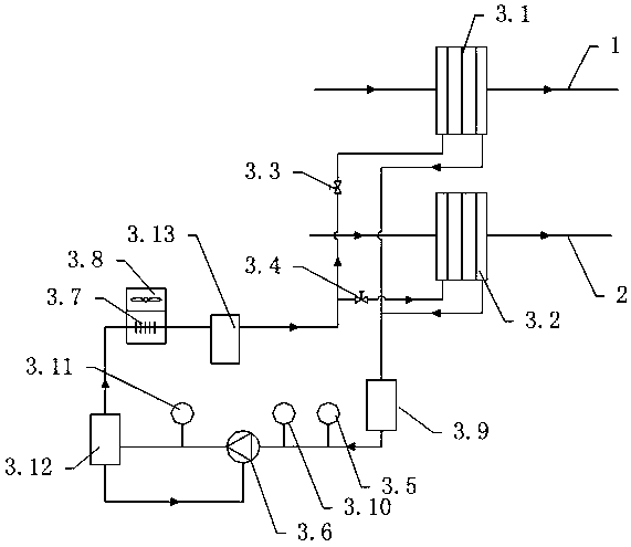
[0047] see Figure 1-2 , a kind of double-air-path central air-conditioning unit provided by the present invention, comprises A air-way air pipe 1, B air-way air pipe 2, several refrigeration systems 3, differential pressure sensor 4 and fan 5; A air-way air pipe and B air-way air pipe The air ducts are connected in parallel between an inlet main air duct 6 and an outlet main air duct 7, the inlet main air duct is connected to the outside, and the outlet main air duct is connected to the air suppl...


PUM


Abstract

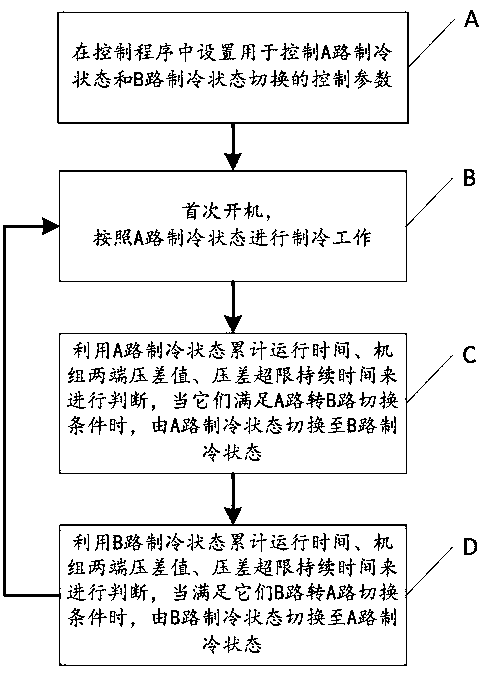
The invention provides a double-air-channel central air-conditioning unit. The double-air-channel central air-conditioning unit comprises an air pipe of an air channel A, an air pipe of an air channelB, a plurality of refrigeration systems, a differential pressure sensor, a fan, a main inlet air pipe, a main outlet air pipe, a first air valve and a second air valve, wherein each refrigeration system is provided with a first evaporator, a second evaporator, a first electromagnetic valve and a second electromagnetic valve. The invention further provides a control method. The control method comprises the following steps: A. setting control parameters; B. working in a refrigeration state of the channel A; C. switching over the refrigeration state of the channel A to a refrigeration state of the channel B when a channel A-channel B switchover condition is met; and D. switching over the refrigeration state of the channel B to the refrigeration state of the channel A when a channel B-channelA switchover condition is met. The unit and the control method thereof are capable of realizing stable and continuous ultra-low-temperature air supply, and avoiding frequent switchover between the air channels, and high in reliability.

Description

technical field [0001] The invention relates to the technical field of central air-conditioning, in particular to a double-air-path central air-conditioning unit and a control method thereof. Background technique [0002] In some special applications, it is necessary to use fresh air and ultra-low temperature air supply to meet certain process requirements. Such applications require that the temperature of the air supply should be within a certain range below zero regardless of the ambient temperature of the outdoor fresh air. Among them - The air supply requirement of 5°C to 0°C is common, and some places require the air supply requirement of -5°C to -10°C. If the air supply temperature of such a low temperature needs to be met, the conventional primary refrigeration system cannot meet the requirements, and multiple cooling systems are required. The way of cascade refrigeration system realizes the low-temperature refrigeration treatment of the supply air temperature, and th...

Claims


Application Information

Patent Timeline
Patent Type & Authority Applications(China)
IPC IPC(8): F24F3/00F24F13/02F24F11/89F24F11/62F24F11/64F24F11/61F24F11/70F24F110/10
CPCF24F3/00F24F11/61F24F11/62F24F11/64F24F11/70F24F11/89F24F13/02F24F2110/10Y02B30/70
Inventor 邱育群黄修力李松
Owner GUANGDONG CONSTR VOCATIONAL TECH INST
Learn More