
Oil well pumping unit directly driven by frameless combined type permanent magnet synchronous motor

A permanent magnet synchronous motor and combined technology, which is applied in the field of oil well pumping units, can solve the problems of large impact of the pipe and rod system, large cost input, low work efficiency, etc., and achieves low energy loss, reduced equipment weight, and fast response speed. Effect

Pending Publication Date: 2019-03-01
HUBEI HUANYEE ELECTROMAGNETIC EQUIP ENG TECH CO LTD
View PDF0 Cites 0 Cited by
  • Summary
  • Abstract
  • Description
  • Claims
  • Application Information

AI Technical Summary

Problems solved by technology

The shortcomings of this conventional beam pumping unit are: poor balance effect, low load rate, low work efficiency, and high energy consumption. In the oil production cost, the electric cost of the pumping unit accounts for about 30%, and the annual power consumption It accounts for 20-30% of the total power consumption of the oil field; at the same time, the dynamic load during operation is relatively large, especially in the process of loading and unloading, which has a large impact on the pipe rod system and is prone to danger; in field applications, conventional Beam pumping units all adopt independent control operation mode, so the initial cost investment in an oil production area is relatively large, and the overall energy consumption of the system is relatively high

Method used


Image

  • Oil well pumping unit directly driven by frameless combined type permanent magnet synchronous motor
  • Oil well pumping unit directly driven by frameless combined type permanent magnet synchronous motor
  • Oil well pumping unit directly driven by frameless combined type permanent magnet synchronous motor

Examples


Embodiment 1

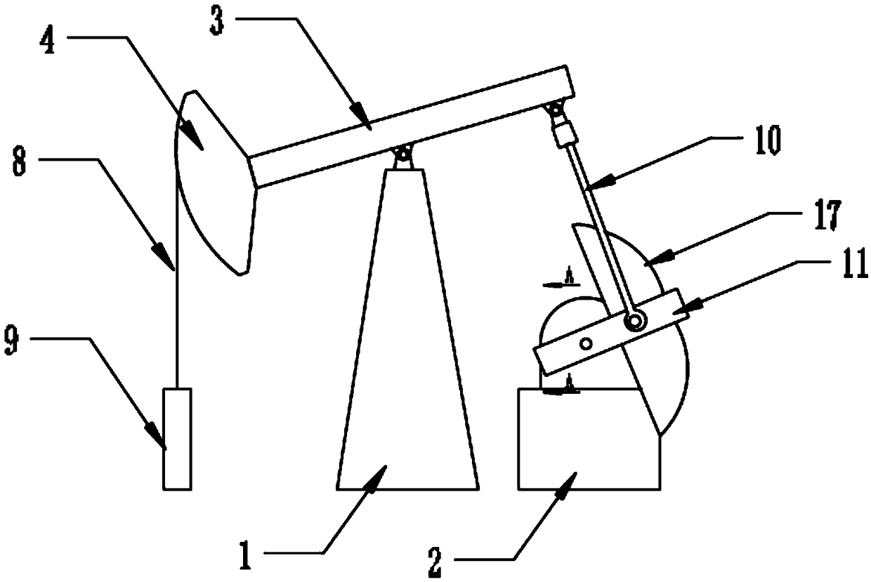
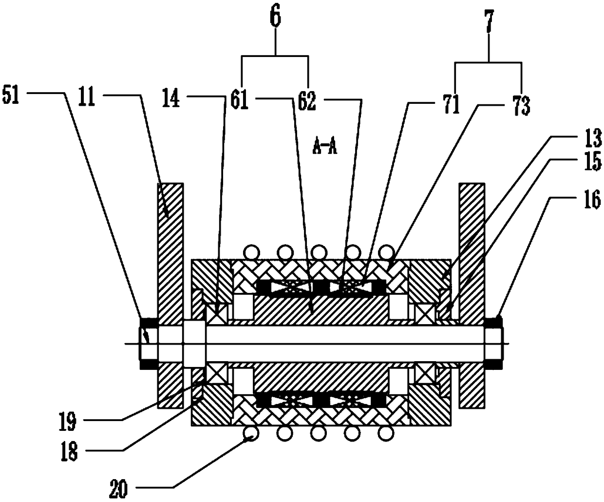
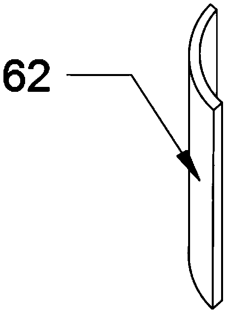
[0028] A frameless combined permanent magnet synchronous motor direct-driven oil well pumping unit described in this embodiment, combined with Figure 1 ~ Figure 4 For illustration, it includes a bracket 1 and a base 2 arranged on the ground, the upper part of the bracket 1 is hinged with the middle part of the beam 3, the front end of the beam 3 is fixed with a donkey head 4, and the donkey head 4 is connected by a wire rope 8 with a suspension rope 9, the lower end surface of the rear end of the beam 3 is hinged with the upper end of the connecting rod 10, and the lower end of the connecting rod 10 is hinged with the driving arm 11, and the driving arm 11 is driven by the frameless combined permanent magnet synchronous motor 5 arranged in the base 2. Direct drive, the driving arm 11 is provided with a counterweight 17; the frameless combined permanent magnet synchronous motor 5 includes a main shaft 51, a stator assembly 7 and a rotor assembly 6, and the driving arm 11 is fix...

Embodiment 2

[0033]A frameless combined permanent magnet synchronous motor direct-driven oil well pumping unit described in this embodiment is basically the same as Embodiment 1, and the difference will be combined Figure 5 ~ Figure 7 To illustrate, the frameless combined permanent magnet synchronous motor 5 includes a main shaft 51, a stator assembly 7 and a rotor assembly 6, the driving arm 11 is fixedly installed on both ends of the main shaft 51 through nuts 16, the stator assembly 7 is fixedly installed in the base 2 and The rotating magnetic field is provided for the rotor assembly 6; the stator assembly 7 is composed of 6 stator units in a fan-shaped block structure, and the stator unit includes the second stator core 72 and the stator winding wound on the second stator core 72, the stator iron The second core 72 is an integrally formed ring-shaped cylindrical disc structure; the rotor assembly 6 with permanent magnet properties is fixedly installed on the main shaft 51 .

[0034] ...

Embodiment 3

[0037] A frameless combined permanent magnet synchronous motor direct-driven oil well pumping unit described in this embodiment is basically the same as Embodiment 1, and the difference will be combined Figure 8 To illustrate, the frameless combined permanent magnet synchronous motor 5 includes a main shaft 51, a stator assembly 7 and a rotor assembly 6, the driving arm 11 is fixedly installed on both ends of the main shaft 51 through nuts 16, the stator assembly 7 is fixedly installed in the base 2 and The rotating magnetic field is provided for the rotor assembly 6; the stator assembly 7 is composed of at least two stator units in a fan-shaped block structure, and the stator unit includes a stator core 71, a stator core 2 72 and a stator core 71 wound on the stator core 1. 1. The stator winding on the stator core two 72, the stator core one 71 is an integrally formed annular columnar structure; the stator core one 71 is an integrally formed annular columnar structure, and th...


PUM


Abstract

The invention discloses an oil well pumping unit directly driven by a frameless combined type permanent magnet synchronous motor. The oil well pumping unit directly driven by the frameless combined type permanent magnet synchronous motor comprises a bracket arranged on the ground and a base arranged on the ground. A rope hanger, a steel wire rope, a horse head, a walking beam, a connecting rod anddriving arms are arranged on the upper part of the bracket, wherein the rope hanger, the steel wire rope, the horse head, the walking beam, the connecting rod and the driving arms are sequentially connected. The upper part of the bracket is hinged to the middle part of the walking beam, the driving arm is directly driven by the frameless combined type permanent magnet synchronous motor in the base, and a counterweight is arranged on the driving arm; the permanent magnet synchronous motor comprises a main shaft, a rotor assembly fixed to the main shaft and having permanent magnetism and a stator assembly installed in the base and providing a rotating magnetic field for the rotor assembly, the driving arms are fixedly installed at two ends of the main shaft; the stator assembly is formed bycombining at least two stator units with a sector block structure; and the stator units comprise stator iron cores and stator windings wound on the stator iron cores. The pumping unit has simple structure, small volume, high transmission efficiency and low energy consumption.

Description

technical field [0001] The invention belongs to the technical field of oilfield development, and in particular relates to a frameless combined permanent magnet synchronous motor direct-driven oil well pumping unit. Background technique [0002] Beam pumping unit has been used for a hundred years since its birth, and is one of the main types of pumping units currently used in oil fields, and is still commonly used in oil fields at home and abroad. Conventional beam pumping units are generally driven by motors, including brackets, beams, donkey heads, rope hangers and counterweights. The middle part of the beam is hingedly mounted on the bracket, and the front end of the beam is fixed with The donkey head is connected to the rope hanger through a steel wire rope. Under the rope hanger, there is an underground oil production device. The rear end of the beam is equipped with a counterweight. The beam between the bracket and the counterweight is movably connected to the motor dri...

Claims


Application Information

Patent Timeline
Patent Type & Authority Applications(China)
IPC IPC(8): E21B43/00H02K7/10
CPCH02K7/10E21B43/00E21B43/121E21B43/127
Inventor 黄诚廖桂芳
Owner HUBEI HUANYEE ELECTROMAGNETIC EQUIP ENG TECH CO LTD
Learn More