Frameless tower crane rotating device directly driven by permanent-magnet synchronous motor
A technology of permanent magnet synchronous motor and rotating device, which is applied to electromechanical devices, cranes, electrical components, etc., can solve the problems of increasing difficulty in design, manufacturing and assembly, large loss of transmission efficiency and accuracy, and increased cost. The effect of improving driving efficiency, fast response speed and reducing loss
- Summary
- Abstract
- Description
- Claims
- Application Information
AI Technical Summary
Problems solved by technology
Method used
Image
Examples
Embodiment 1
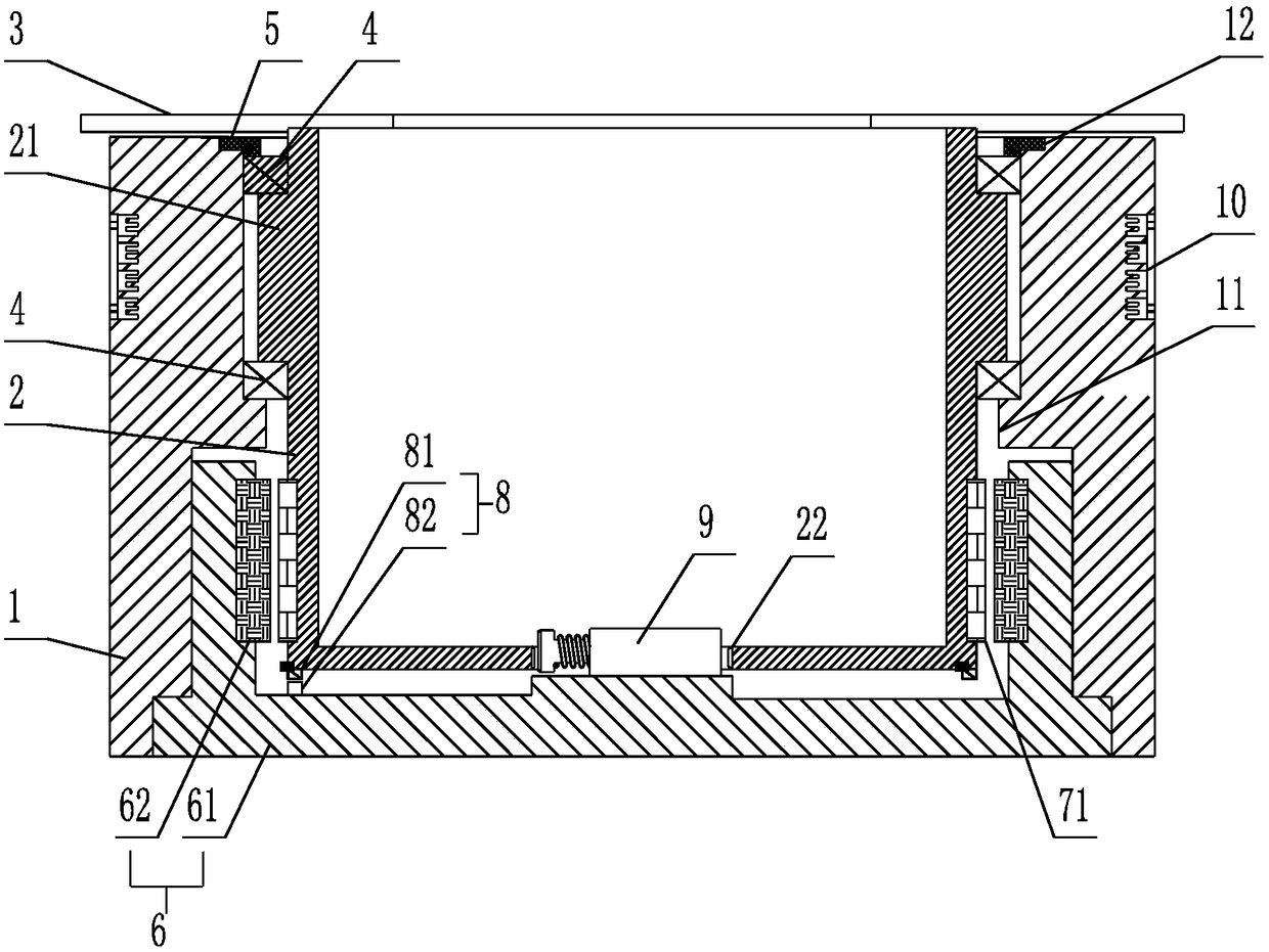
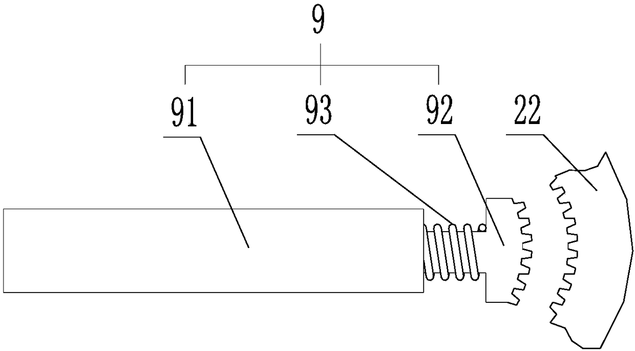
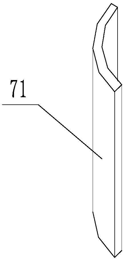
[0029] Such as Figure 1-3 As shown, a frameless permanent magnet synchronous motor direct-driven tower crane rotating device, the tower crane rotating device includes a base 1, a rotating shaft 2 and a platform seat 3; the platform seat 3 is fixedly installed on the rotating shaft 2 , the rotating shaft 2 is fixed in the base 1 through a bearing 4, the rotating shaft 2 is directly driven by a frameless permanent magnet synchronous motor, and the frameless permanent magnet synchronous motor includes a stator assembly 6 and a rotor assembly 7 The stator assembly 6 is fixedly installed on the base 1 to provide a rotating magnetic field for the rotor assembly 7; the rotor assembly 7 with permanent magnet properties is fixedly installed on the rotating shaft 2;
[0030] Wherein, the stator assembly 6 includes a stator core 1 62 and a stator winding wound on the stator core 1 62, and the stator core 1 62 is an annular cylindrical structure integrally processed.
[0031]As a prefer...
Embodiment 2
[0034] Such as Figure 5-7 As shown, a frameless permanent magnet synchronous motor direct-driven tower crane rotating device, the tower crane rotating device includes a base 1, a rotating shaft 2 and a platform seat 3; the platform seat 3 is fixedly installed on the rotating shaft 2 , the rotating shaft 2 is fixed in the base 1 through a bearing 4, the rotating shaft 2 is directly driven by a frameless permanent magnet synchronous motor, and the frameless permanent magnet synchronous motor includes a stator assembly 6 and a rotor assembly 7 The stator assembly 6 is fixedly installed on the base 1 to provide a rotating magnetic field for the rotor assembly 7; the rotor assembly 7 with permanent magnet properties is fixedly installed on the rotating shaft 2;
[0035] Wherein, the stator assembly 6 includes a second stator core 63 and a stator winding wound on the second stator core 63 , and the second stator core 63 is an annular disc structure integrally processed.
[0036] A...
Embodiment 3
[0039] Such as Figure 8 As shown, a frameless permanent magnet synchronous motor direct-driven tower crane rotating device, the tower crane rotating device includes a base 1, a rotating shaft 2 and a platform seat 3; the platform seat 3 is fixedly installed on the rotating shaft 2 , the rotating shaft 2 is fixed in the base 1 through a bearing 4, the rotating shaft 2 is directly driven by a frameless permanent magnet synchronous motor, and the frameless permanent magnet synchronous motor includes a stator assembly 6 and a rotor assembly 7 The stator assembly 6 is fixedly installed on the base 1 to provide a rotating magnetic field for the rotor assembly 7; the rotor assembly 7 with permanent magnet properties is fixedly installed on the rotating shaft 2;
[0040] Wherein, the stator assembly 6 includes a stator core 1 62 and a stator core 2 63, and the stator core 1 62 and the stator core 2 63 are respectively wound with stator windings; the stator core 1 62 is an integrally ...
PUM
 Abstract
Description
Claims
Application Information
 - R&D
- Intellectual Property
- Life Sciences
- Materials
- Tech Scout
- Unparalleled Data Quality
- Higher Quality Content
- 60% Fewer Hallucinations
Browse by: Latest US Patents, China's latest patents, Technical Efficacy Thesaurus, Application Domain, Technology Topic, Popular Technical Reports.
© 2025 PatSnap. All rights reserved.Legal|Privacy policy|Modern Slavery Act Transparency Statement|Sitemap|About US| Contact US: help@patsnap.com


