
Machining platform and cast iron platform

A technology of cast iron platform and processing platform, applied in the platform field, can solve the problems of easy offset and unstable installation, etc.

Active Publication Date: 2019-03-01
大连巨人北斗高新技术开发有限公司
View PDF9 Cites 2 Cited by
  • Summary
  • Abstract
  • Description
  • Claims
  • Application Information

AI Technical Summary

Problems solved by technology

[0002] Cast iron flat plate is also called cast iron platform, the appearance is basically a box type, the working surface is rectangular, square, circular, etc., the material is HT200-300, QT400-600, using scraping technology, the working surface can be processed V-shaped, T Shaped, U-shaped grooves, dovetail grooves, round holes, long holes, etc., are used for workpieces, equipment testing, scribing, assembly, welding, assembly, and riveting. The ideal plane is placed in the middle of the actual surface according to the trend of the actual surface, and the sum of the squares of the distances from each point on the actual surface to the ideal plane is the smallest, and the center plane of the least square is used as the evaluation base plane. The difference between the maximum value and the minimum value in the plane deviation is the measured surface flatness error value. The diagonal principle uses a plane that passes through one diagonal line of the measured surface and is parallel to the other diagonal line as the evaluation base plane. The difference between the maximum value and the minimum value in this plane deviation is the flatness error value of the measured surface, but it is not firm during installation, and it is also prone to offset

Method used

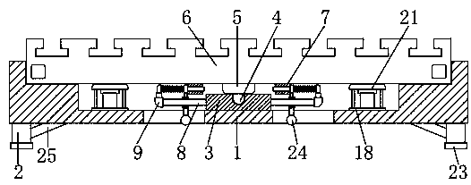
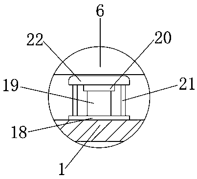
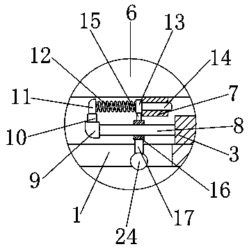

Image

  • Machining platform and cast iron platform
  • Machining platform and cast iron platform
  • Machining platform and cast iron platform

Examples


Embodiment Construction

[0014] The following will clearly and completely describe the technical solutions in the embodiments of the present invention with reference to the accompanying drawings in the embodiments of the present invention. Obviously, the described embodiments are only some, not all, embodiments of the present invention. Based on the embodiments of the present invention, all other embodiments obtained by persons of ordinary skill in the art without making creative efforts belong to the protection scope of the present invention.

[0015] see Figure 1-3 , the present invention provides a technical solution: a processing platform and a cast iron platform, including a platform groove 1, the platform groove 1 is used to fix the cast iron platform 6, the left and right sides of the bottom of the platform groove 1 are fixedly connected with supporting legs 2, the platform The slot 1 is supported on the ground by the outrigger 2, and the center of the inner end of the outrigger 2 is fixedly c...


PUM


Abstract

The invention discloses a machining platform and a cast iron platform. The machining platform comprises a platform groove. Support legs are fixedly connected to the left side and the right side of thebottom end of the platform groove correspondingly. The bottom of the outer wall of the cast iron platform is attached to the inner wall of the platform groove. Sleeving blocks are fixedly connected to the left side and the right side of the bottom end of the cast iron platform correspondingly. Sliding rods are fixedly connected to the centers of the left end and the right end of the outer wall ofa groove correspondingly. Stop blocks are fixedly connected to the ends of the outer sides of sliding blocks. A third inner block is fixedly connected to the center of the bottom end of each push block. Each sliding block is fixedly connected to the bottom end of the corresponding third inner block. The center of the inner wall of each sliding block is connected to the center of the outer wall ofthe corresponding sliding rod in a sleeving manner. A pull rod is fixedly connected to the center of the bottom end of each sliding block. According to the machining platform and the cast iron platform, when the cast iron platform needs to be fixed, firm mounting can be achieved through matching of the platform groove and the sleeving blocks; and meanwhile, a fixing structure is additionally arranged, so that the cast iron platform is connected more stably.

Description

technical field [0001] The invention relates to the technical field of platforms, in particular to a processing platform and a cast iron platform. Background technique [0002] Cast iron flat plate is also called cast iron platform, the appearance is basically a box type, the working surface is rectangular, square, circular, etc., the material is HT200-300, QT400-600, using scraping technology, the working surface can be processed V-shaped, T Shaped, U-shaped grooves, dovetail grooves, round holes, long holes, etc., are used for workpieces, equipment testing, scribing, assembly, welding, assembly, and riveting. The ideal plane is placed in the middle of the actual surface according to the trend of the actual surface, and the sum of the squares of the distances from each point on the actual surface to the ideal plane is the smallest, and the center plane of the least square is used as the evaluation base plane. The difference between the maximum value and the minimum value i...

Claims


Application Information

Patent Timeline
IPC IPC(8): B25H1/00
CPCB25H1/00
Inventor 刘俊李鹤黄一沫
Owner 大连巨人北斗高新技术开发有限公司
Learn More