
Device and method for chain demounting

A chain and driving device technology, applied in the direction of repairing chain tools, metal chains, manufacturing tools, etc. by metal processing methods, can solve problems such as troublesome, small tension, and long time required to avoid damage and offset torque , the effect of improving work efficiency

Pending Publication Date: 2019-03-01
北京天瑞星光热技术有限公司
View PDF0 Cites 3 Cited by
  • Summary
  • Abstract
  • Description
  • Claims
  • Application Information

AI Technical Summary

Problems solved by technology

[0002] In daily life, chain transmission is one of the three major mechanical transmission methods. It has no elastic sliding and slipping, can maintain an accurate average transmission ratio, requires small tension, and the pressure on the shaft is also small, which can reduce The friction loss of the bearing, when the center distance between the driving wheel and the driven wheel is required to be large, its transmission structure is simple, and it can work under harsh environmental conditions such as high temperature and oil pollution, and is widely used in industrial machinery, agricultural machinery, and machine tools. In the chain repair and maintenance work, ordinary tools such as hammers and pliers are generally used to knock the chain pin to achieve the purpose of disassembly. However, this traditional method often takes a long time and is easy to cause physical deformation of the chain. During the disassembly process, single-point positioning is adopted, and only the pin shaft of the chain is positioned. Since the length of the chain in use is relatively long, the positioning is affected by the torsion of the entire chain during positioning. trouble

Method used


Image

  • Device and method for chain demounting
  • Device and method for chain demounting
  • Device and method for chain demounting

Examples


Embodiment Construction

[0027] Embodiments of the present invention will be further described in detail below in conjunction with the accompanying drawings and examples. The following examples are used to illustrate the present invention, but should not be used to limit the scope of the present invention.

[0028] In the description of the present invention, unless otherwise stated, the meaning of "plurality" is two or more; the terms "upper", "lower", "left", "right", "inner", "outer" , "front end", "rear end", "head", "tail", etc. indicate the orientation or positional relationship based on the orientation or positional relationship shown in the drawings, and are only for the convenience of describing the present invention and simplifying the description, rather than Nothing indicating or implying that a referenced device or element must have a particular orientation, be constructed, and operate in a particular orientation should therefore not be construed as limiting the invention. In the descrip...


PUM


Abstract

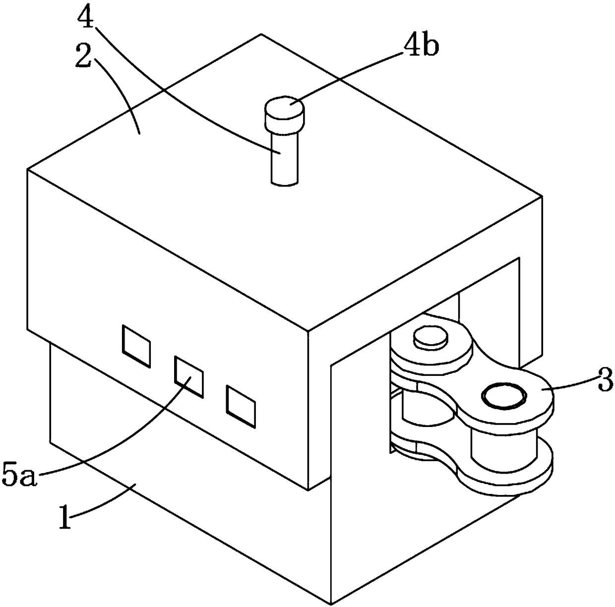
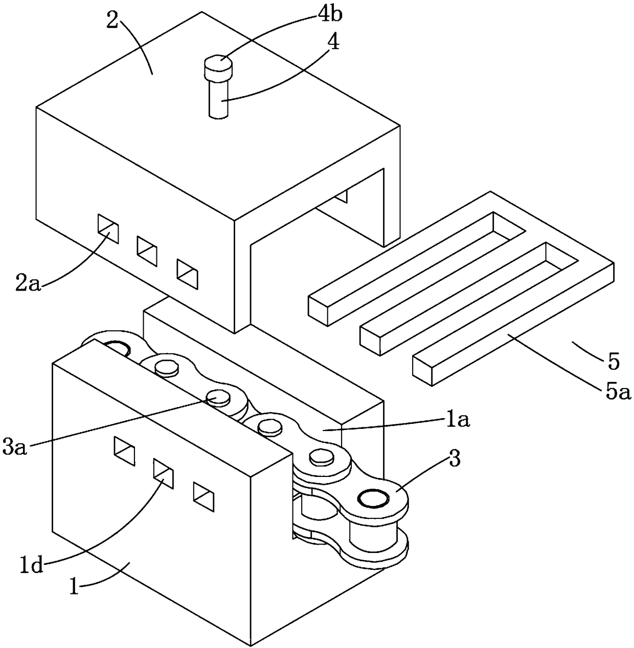
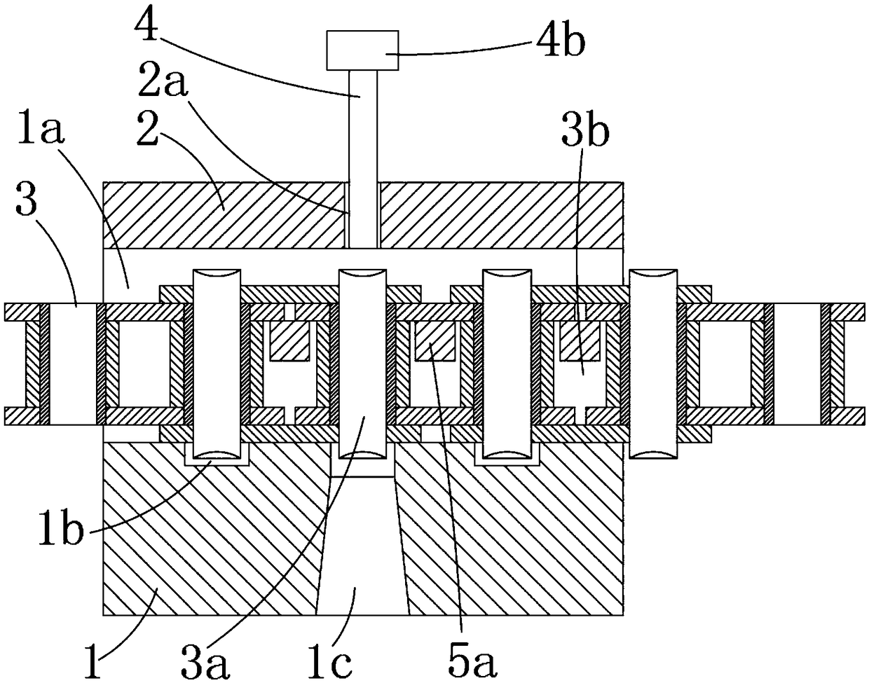
The device discloses a device for chain demounting. The device comprises a bearing base and a buckle cover. The bearing base is provided with a placing groove where a chain is placed, avoiding groovesmatched with pin shafts of the chain are arranged at the bottom of the placing groove, a discharge hole communicates with the bottom of the avoiding groove located in the middle, an ejection shaft used for ejecting out the pin shaft located over the discharge hole is arranged on the buckle cover in an up-down moving mode, and the bearing base and the buckle cover are connected through a supporting device. In the operation process, chain sections on the two sides of the pin shaft to be demounted are directly positioned, chain torque is effectively neutralized, no extra staff is needed for auxiliary operation, the demounting process can be completed through one person, the working efficiency is improved, and the chain is prevented from being damaged in the demounting process.

Description

technical field [0001] The invention relates to the technical field of chain removal tools, in particular to a device and method for chain removal. Background technique [0002] In daily life, chain drive is one of the three major mechanical transmission methods. It has no elastic sliding and slipping, can maintain an accurate average transmission ratio, requires less tension, and has less pressure on the shaft, which can reduce The friction loss of the bearing, when the center distance between the driving wheel and the driven wheel is required to be large, the transmission structure is simple, and it can work under harsh environmental conditions such as high temperature and oil pollution, and is widely used in industrial machinery, agricultural machinery, and machine tools. In chain repair and maintenance work, ordinary tools such as hammers and pliers are generally used to knock the chain pin to achieve the purpose of disassembly. Single-point positioning is adopted durin...

Claims


Application Information

Patent Timeline
Patent Type & Authority Applications(China)
IPC IPC(8): B21L21/00
CPCB21L21/00
Inventor 曹洪智付雷郭大威郑泽勇庞文猛魏晓瑞
Owner 北京天瑞星光热技术有限公司
Learn More