
Servo motor with protection structure

A servo motor and protective structure technology, applied in the field of servo motors, can solve problems such as weak protection, demagnetization, and inability to solve demagnetization, and achieve the effect of offsetting torque, increasing heat dissipation, and facilitating alignment and compensation.

Active Publication Date: 2022-07-22
佛山登奇伺服科技有限公司 +1
View PDF15 Cites 0 Cited by
  • Summary
  • Abstract
  • Description
  • Claims
  • Application Information

AI Technical Summary

Problems solved by technology

[0003] In order to overcome the shortcomings of the weak protection of the motor body in the prior art, the Chinese utility model patent with the publication number CN212163002U discloses a drive motor with a shell protection mechanism, including a drive motor body, the front and back of the drive motor body are horizontal A reinforcement plate is bolted, and a guide cylinder is bolted to both sides of the front and back of the reinforcement plate. A guide column, the end of the guide column away from the limit spring is bolted to the first protective plate
Although the device achieves the effect of elastic buffer protection, the temperature of the servo motor will gradually rise during operation, and the servo motor will demagnetize when it is in a high temperature state for a long time. This device cannot solve the problem of demagnetization caused by high temperature

Method used


Image

  • Servo motor with protection structure
  • Servo motor with protection structure
  • Servo motor with protection structure

Examples


Embodiment

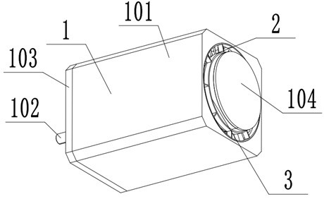
[0025] Example: as Figure 1-Figure 8 The shown servo motor with a protective structure includes a motor body assembly 1 and a heat dissipation and cooling assembly 2 , and the heat dissipation and cooling assembly 2 is installed inside the motor body assembly 1 .

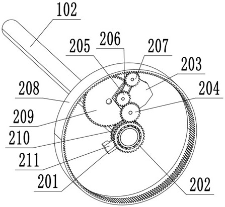
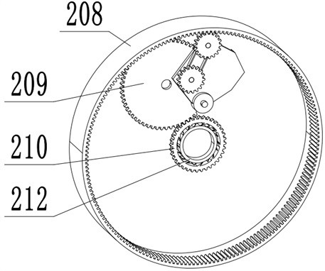
[0026] The motor body assembly 1 includes a motor shaft 102 and a rear base 105. The motor shaft 102 is rotatably mounted on the rear base 105; the heat dissipation and cooling assembly 2 includes a rear inner ratchet 201, a rear outer ratchet 202, a front inner ratchet 212, and a front end. The outer ratchet 210, the rear gear set, the outer gear ring 208, the large gear 209, the rear cooling fan 213, the rear gear set, the outer gear ring 208, and the large gear 209 are all rotatably installed on the rear base 105. The inner ratchet wheel 201 at the end and the inner ratchet wheel 212 at the front end are stacked and fixed on the motor shaft 102. The inner ratchet wheel 201 at the rear end, the outer ratchet whee...


PUM


Abstract

The invention discloses a servo motor with a protection structure, and relates to the technical field of driving motors, and the servo motor comprises a motor body assembly, a heat dissipation and cooling assembly and a rotation speed detection assembly. The heat dissipation cooling assembly comprises a rear-end inner ratchet wheel, a rear-end outer ratchet wheel, a front-end inner ratchet wheel, a front-end outer ratchet wheel, a rear-end gear set, an outer-end gear ring, a large gear and a rear-end heat dissipation fan, the rear-end gear set, the outer-end gear ring and the large gear are all rotationally installed on the rear machine base, and the rear-end inner ratchet wheel and the front-end inner ratchet wheel are fixedly installed on a motor shaft in a stacked mode; the rear-end inner ratchet wheel is meshed with the rear-end outer ratchet wheel, the input end of the rear-end gear set is in gear fit with the rear-end outer ratchet wheel, and the output end of the rear-end gear set is in gear fit with the outer-end gear ring; the rear-end cooling fan is fixedly connected with the outer-end gear ring and can rotate together with the outer-end gear ring, the temperature of the motor in an actual power environment is reduced through rotation of the rear-end cooling fan, the demagnetization threshold value is increased, and demagnetization is reduced.

Description

technical field [0001] The invention relates to the technical field of drive motors, in particular to a servo motor with a protective structure. Background technique [0002] Servo motor refers to the engine that controls the operation of mechanical components in the servo system, and is an auxiliary motor indirect speed change device. The servo motor can control the speed, the position accuracy is very accurate, and the voltage signal can be converted into torque and speed to drive the control object. The rotor speed of the servo motor is controlled by the input signal and can respond quickly. In the automatic control system, it is used as an executive element, and has the characteristics of small electromechanical time constant and high linearity. It can convert the received electrical signal into the motor shaft. angular displacement or angular velocity output. Servo motors are divided into two categories: DC and AC servo motors. The main feature is that when the signal...

Claims


Application Information

Patent Timeline
Patent Type & Authority Applications(China)
IPC IPC(8): H02K9/06H02K11/215H02K7/10H02K7/116
CPCH02K9/06H02K11/215H02K7/1016H02K7/116
Inventor 董明海文益雪向红斌
Owner 佛山登奇伺服科技有限公司
Learn More