
On-line identification method of photographic rotational speed of rotating equipment

A technology of rotating equipment and identification method, applied in the direction of devices using optical methods, etc., can solve problems such as inability to stop, and achieve the effect of ensuring normal operation and overcoming inability to stop

Active Publication Date: 2020-11-03
SHANGHAI JINYI INSPECTION TECH
View PDF5 Cites 0 Cited by
  • Summary
  • Abstract
  • Description
  • Claims
  • Application Information

AI Technical Summary

Problems solved by technology

[0003] The technical problem to be solved by the present invention is a method for on-line identification of the camera-type rotational speed of rotating equipment. This method overcomes the defect that the traditional rotational speed measurement cannot be stopped, and can obtain the rotational speed of the equipment rotating body flexibly and conveniently online, achieving the accuracy of the rotational speed of the equipment. Real-time detection ensures the normal operation of vibration diagnosis

Method used


Image

  • On-line identification method of photographic rotational speed of rotating equipment
  • On-line identification method of photographic rotational speed of rotating equipment

Examples


Embodiment Construction

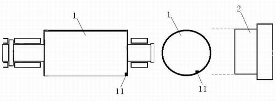
[0023] Example figure 1 with figure 2 As shown, the photographic rotating speed online identification method of rotating equipment of the present invention comprises the following steps:

[0024] Step 1. Set up a camera system 2 with continuous shooting function on one side of the equipment rotating body 1, and at the same time identify a feature point 11 on the outer edge of the equipment rotating body 1;

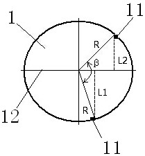
[0025] Step 2: Set the continuous shooting speed of the camera system 2 to 5 frames per second, and take pictures of the rotating body 1, take the first and second photos, and the angle that the rotating body 1 turns within 1 / 5 second is The angle β between the feature point 11 in the first photo and the feature point 11 in the second photo along the direction of rotation plus n times 360 degrees, where n=0,1,2,3,4... ;

[0026] Step 3: Calculate the included angle β by measuring the vertical distance from the feature point 11 to the axis 12 in the photograph and the r...


PUM


Abstract

The invention discloses a photographic speed on-line identification method for rotating equipment. The method comprises the following steps: a photographing system with a continuous shooting function is used to continuously and quickly take clear images of an equipment rotator at equal intervals; three continuous shooting speeds are set; a feature point with obvious features of the rotator is selected from the images taken, and the position changes of the feature point in two consecutive images are compared and measured; and finally, the angular velocity of the feature point is calculated according to the continuous capture speed, and the speed of the equipment can be obtained through conversion and comparison with the rated speed of the equipment. The method overcomes the defect that equipment cannot be shut down in traditional speed measurement, and can be used to flexibly and conveniently acquire the speed of an equipment rotator online. Real-time detection of equipment speed is realized, and normal vibration diagnosis is ensured.

Description

technical field [0001] The invention relates to a photographic rotation speed online identification method of rotating equipment. Background technique [0002] In the field of vibration diagnosis of rotary mechanical equipment, it is often necessary to accurately obtain the rotational speed of the equipment. At present, the main measuring equipment is a photoelectric tachometer. When the photoelectric tachometer measures the speed, it usually needs to stop the equipment, and paste light reflective paper on the surface of its rotating body, and then start the equipment. The photoelectric tachometer measures the equipment through the light reflective paper. The rotational speed of the rotating body. However, for equipment that cannot be stopped, the photoelectric tachometer cannot measure the rotational speed due to the inability to paste the light-reflecting paper, which affects the normal vibration diagnosis work. Contents of the invention [0003] The technical problem ...

Claims


Application Information

Patent Timeline
Patent Type & Authority Patents(China)
IPC IPC(8): G01P3/38
Inventor 展宇
Owner SHANGHAI JINYI INSPECTION TECH
Learn More