Indication of resource location, method and device for receiving
A resource location and resource technology, applied in the field of communication, can solve the problem that the base station cannot indicate the location of BWP resources
- Summary
- Abstract
- Description
- Claims
- Application Information
AI Technical Summary
Problems solved by technology
Method used
Image

Examples
Embodiment 1
[0054] Provides an indication of a location of resources in the method of the present embodiment, figure 2 The method of indicating the resource location is an embodiment of the present invention, a flow chart, such as figure 2 As shown, the process includes the following steps:
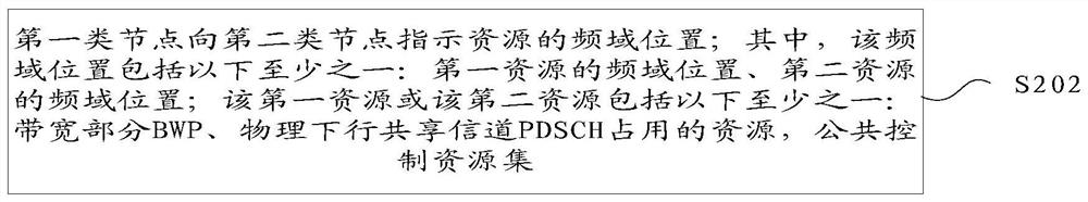
[0055] Step S202, the first type node transmits resource location information to the second class node, the resource location information indicating the location of at least the frequency domain resource; wherein the frequency domain comprises at least one of the following positions: a first position of the frequency domain resource , a frequency domain location of the second resource; resource of the first or the second resources comprise at least one of the following: bandwidth part BWP, PDSCH physical downlink shared channel resources occupied by the common set of control resources.
[0056] Alternatively, the step of performing a first main body of the node may be a base station type, such as concret...
Embodiment 2
[0105] This alternative embodiment describes the frequency domain position of the first resource using an offset with respect to the reference point, using an offset relative to the first resource frequency domain.
[0106] like Figure 4Gives SS block, PDSCH and Common CORESET position NR the frequency domain carrier, wherein, k1, k2 and k3 respectively SS block, PDSCH and the center frequency of Common CORESET corresponding to subcarrier number, the base station may use Common CORESET PDCCH scheduling a PDSCH resources occupied bearer. A first resource to the resource occupied by the PDSCH as an example, Common CORESET second resource to an example, the reference point to the center of SS block as an example. Examples base station indicates to the terminal of the present embodiment PDSCH center frequency offset with respect to the center frequency shift and the SS block PDSCH bandwidth point, and the center frequency of Common CORESET relative to the center frequency of the PDSCH...
Embodiment 3
[0117] The present alternative embodiment described with respect to the frequency domain using the offset indicates the position of the first resource on the frequency domain reference point, the second node is calculated according to predefined rules frequency domain position of the second resource.
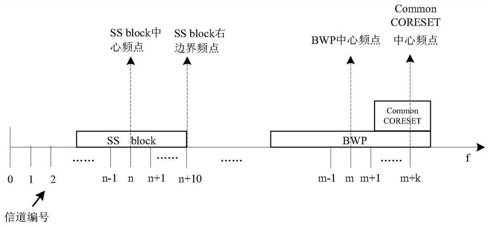
[0118] like Figure 5 Gives SS block, BWP and Common CORESET position NR the frequency domain carrier. In a first resource BWP, for example, Common CORESET second resource to an example, the reference point to the center of SS block as an example. In the present embodiment, the base station indicates to the terminal of the center frequency BWP SS block with respect to the bandwidth of the center frequency offset and the BWP, CommonCORESET bandwidth indication comprises a relatively specific content subcarrier number, and right and left offset indicates a bandwidth, as shown in table 5, wherein - denotes the entry does not exist.
[0119] Wherein the center BWP frequency point relativ...
PUM
 Abstract
Description
Claims
Application Information
 - R&D
- Intellectual Property
- Life Sciences
- Materials
- Tech Scout
- Unparalleled Data Quality
- Higher Quality Content
- 60% Fewer Hallucinations
Browse by: Latest US Patents, China's latest patents, Technical Efficacy Thesaurus, Application Domain, Technology Topic, Popular Technical Reports.
© 2025 PatSnap. All rights reserved.Legal|Privacy policy|Modern Slavery Act Transparency Statement|Sitemap|About US| Contact US: help@patsnap.com