
Light emitting device, backlight module applying the same, light source module and preparation method thereof

A technology of light emitting device and light source module, which is applied in the direction of electrical components, electric solid devices, circuits, etc., and can solve the problems of reducing the luminous brightness and luminous efficiency of the light emitting device, side light leakage, etc.

Active Publication Date: 2019-02-26
吴裕朝
View PDF3 Cites 0 Cited by
  • Summary
  • Abstract
  • Description
  • Claims
  • Application Information

AI Technical Summary

Problems solved by technology

However, this modification method is not easy to make the luminescent powder completely and uniformly cover the sides of the LED crystal grains, and it is easy to cause light leakage from the sides, thereby reducing the luminous brightness and luminous efficiency of the light-emitting device.

Method used

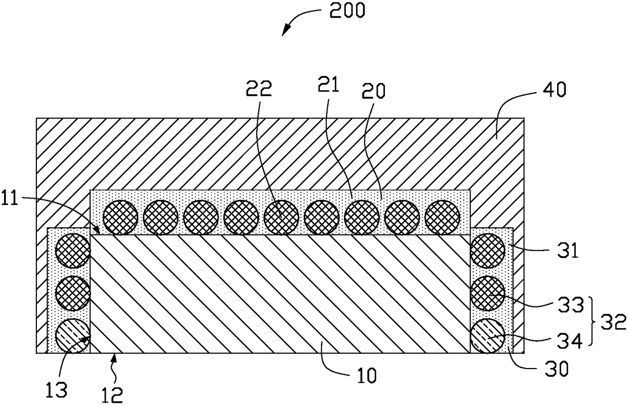
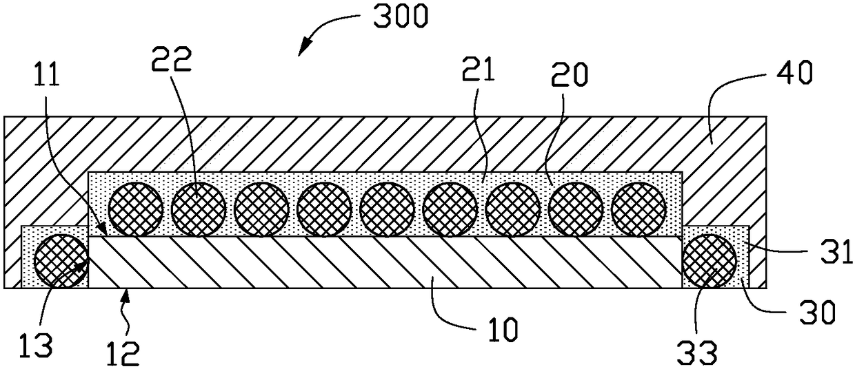

Image

  • Light emitting device, backlight module applying the same, light source module and preparation method thereof
  • Light emitting device, backlight module applying the same, light source module and preparation method thereof
  • Light emitting device, backlight module applying the same, light source module and preparation method thereof

Examples


no. 1 example

[0121] see Figure 11 and Figure 12 , the manufacturing method of the first embodiment of the light-emitting device 100 of the present invention, which includes the following steps:

[0122] Step S101, providing a plurality of light emitting chips 10, each light emitting chip 10 has an upper surface 11, a lower surface 12 and a side surface 13;

[0123] Step S102, adhering the lower surface 12 of the light-emitting chip 10 on an expansion film 50;

[0124] Step S103, uniformly dispersing microbeads 32 in the gap formed between the upper surface 11 of the light-emitting chip 10 and the adjacent light-emitting chip 10;

[0125] Step S104, removing microbeads 32 that are not adhered to the expanded membrane 50;

[0126] Step S105, applying the liquid phase containing the luminescent powders 21, 31 to the upper surface 11 of the luminescent chip 10 and the gap formed between the adjacent luminescent chips 10;

[0127] Step S106, removing the liquid so that the luminescent pow...


PUM

PropertyMeasurementUnit
Particle sizeaaaaaaaaaa

Abstract

The invention provides a light emitting device. The light emitting device comprises a light emitting wafer, a light emitting layer and a light conducting layer. The light emitting wafer comprises an upper surface and a side face. The light emitting layer is formed on the upper surface of the light emitting wafer. The light conducting layer is formed on the side face of the light emitting wafer. The light emitting layer comprises multiple light emitting powder grains and multiple micro beads. The light emitting layer and the light conducting layer do not include adhesion agent. The invention also further provides a backlight module applying the same, a light source module and a preparation method of the light emitting device. According to the invention, light leakage of the side face of thelight emitting wafer can be reduced, so the light emitting efficiency of the light emitting device is improved. In addition, preparation technique is simple, and the cost is quite low.

Description

technical field [0001] The invention relates to a light emitting device, a backlight module using the same, a light source module and a preparation method thereof. Background technique [0002] Light Emitting Diode (LED for short) has the advantages of high brightness, small size, light weight, unbreakable, low power consumption and long life, so it is widely used in various light emitting products and display products. The principle of light emission is mainly by applying a voltage to the diode to drive the electrons and holes in the diode to combine, and the energy generated by the combination is released in the form of light. In addition, the existing light-emitting devices mainly adjust the wavelength (color) and intensity of light by modifying the surface of the light-emitting diode grains. [0003] In the use of light-emitting diodes, the traditional method is mainly to mix luminescent powder into resin and then coat it on the crystal grains of light-emitting diodes. ...

Claims


Application Information

Patent Timeline
IPC IPC(8): H01L25/075H01L33/48H01L33/58H01L33/60
CPCH01L25/0753H01L33/48H01L33/58H01L33/60H01L25/075
Inventor 吴裕朝刘艳吴冠辰吴冠伟
Owner 吴裕朝
Learn More